Flexible PCB Assembly manufacturer for boards up to 1200mm length
By PCBA PrototypePublished On: 2026-07-06Categories: Blog0 Comments on Flexible PCB Assembly manufacturer for boards up to 1200mm length
By PCBA PrototypePublished On: 2026-07-06Categories: Blog0 Comments on Flexible PCB Assembly manufacturer for boards up to 1200mm length

Some information about Flexible PCB Assembly manufacturer for boards up to 1200mm length:
| Type | PCB & PCB Assembly |
| Industry experience | 15+years |
| Place of Origin | China |
| Company Name | GREATPCB |
| Product Features | Environmentally Friendly,Higher Efficiency,Color Options,High Qulity,High integration,Longer Lifespan,Vibration resistant… |
| Certificate | IS045001,ISO 9001:2015,IS013485,ITAR REGISTERED,MIL-PRF-31032… |
| OEM/ODM | Support |
| Surface treatment | ENEPIG,ENIG,HASL,Electrolytic Hard Gold,ImSn… |
| Application | Computers & Networks,Automotive Electronics,Industrial Control,Communication Equipment,AI & Data Center,Consumer Electronics,Medical Equipment…etc |
| Design Software | AutoCAD,Cadence Allegro,Protel,Altium Designer… |
| Payment | Visa,DISCOVER,paypal,Marst…etc |
| Nearby ports | Shenzhen,Guangzhou… |
| Warranty | 1 year |
| One Stop Services | Sourcing Components ,Programming IC,Conformal Coating, Function and Aging Testing |
| Transportation | DHL,EMS,ARAMEX,TNT…etc |
| Packing Size | 81 * 25 * 92 According to container size, standard export package |
| Terms of delivery | T/T,L/C,Cash,Western Union… |
| Operating Temperature | -40°C to 125°C |
| Solder mask Color | Blue,Grey,Yellow, or according to customer requirements |
| Material | FR4 /aluminum/ceramic CEM1 |
| After-sales Service | Online support |
| Trading Country | South america,Europe,Africa,Mid east,Russia,UK,Argentina,Norway,British,the USA… |
| Selling Units | Single item |
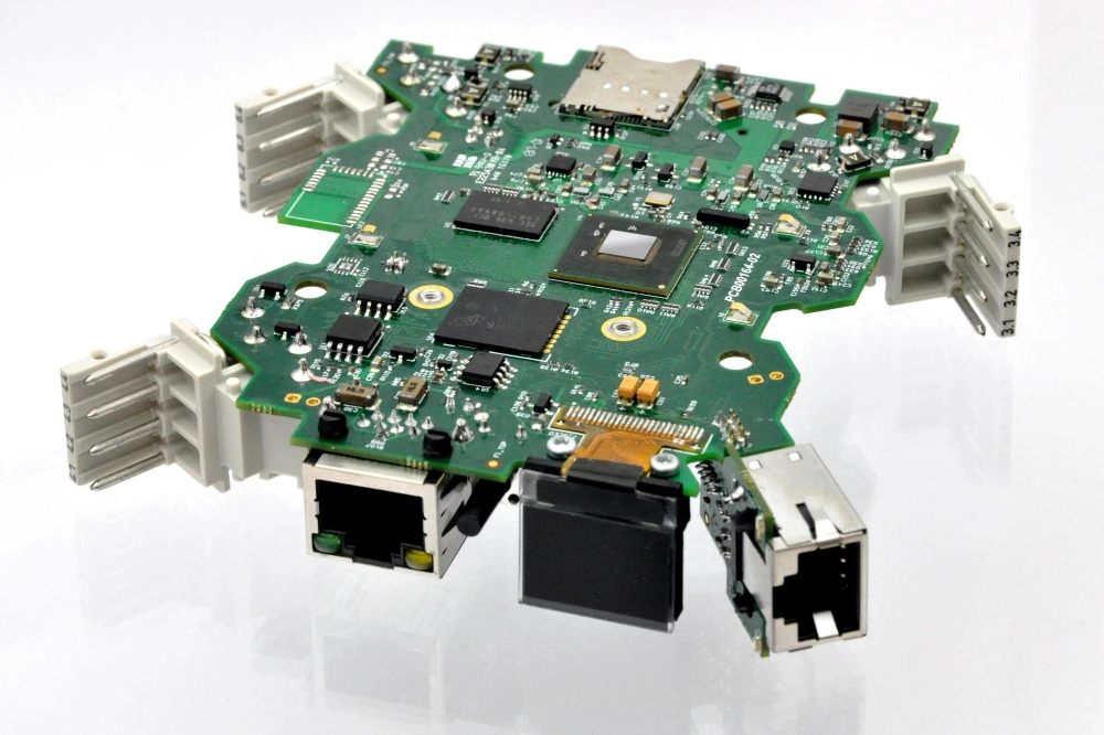
Some PCB & Switch Module & Elevator Relay

Our workshop for Flexible PCB Assembly manufacturer for boards up to 1200mm length

Advanced PCB manufacturing equipments

The test for Flexible PCB Assembly manufacturer for boards up to 1200mm length

Table of Contents

Tags