What is Flexible PCB?
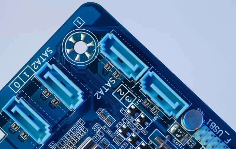
A flexible printed circuit board (FPC), also known as a flexible PCB or flexible circuit board, is a bendable circuit board. Unlike traditional rigid circuit boards, which are inflexible, flexible PCBs use flexible substrates and copper foils. Common materials include polyimide and polyester films, which provide high flexibility and foldability. In modern electronics manufacturing, flexible PCBs have become indispensable due to their lightweight and bendable properties. They are widely used in high-density devices such as smartphones and laptops.

Advantages of Flexible PCB over Rigid PCB
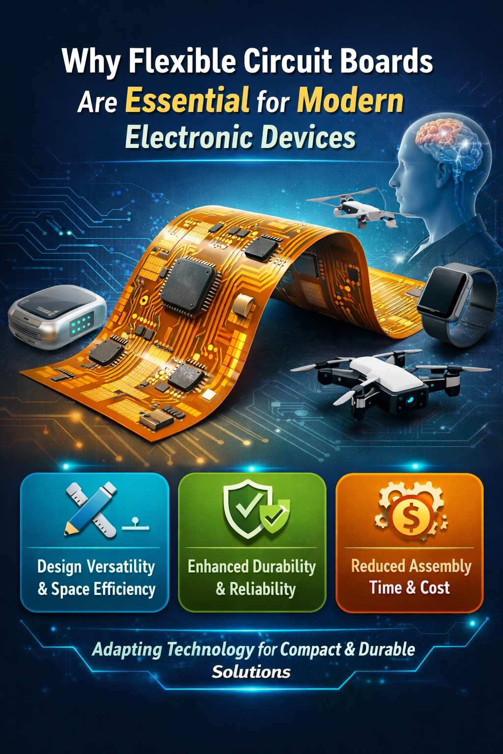
- High Flexibility: Flexible PCBs, often made from polyimide flex PCB material, provide great flexibility. Early flip and sliding phones utilized flexible printed circuits, allowing for repeated bending and flexible arrangement. This makes them suitable for complex spatial environments.
- Lightweight: Compared to traditional rigid PCBs, flexible PCB boards are much thinner and lighter. Rigid PCBs typically range from 0.4 to 3 mm in thickness, whereas flexible PCBs are generally between 0.07 and 0.4 mm. This significant reduction in thickness is why flexible PCBs are frequently used in portable devices.
- Space Saving: Rigid PCBs require more space and cannot be overly complex in mounting. Flexible printed circuits, due to their thin and flexible nature, have minimal space requirements and high integration density. They can integrate multiple traditional circuit boards into a single flexible PCB, reducing the need for connectors and cables, which further saves space and weight.
Disadvantages of Flexible PCB
- High Manufacturing Costs: The materials used in flexible PCB manufacturing, such as polyimide, are more expensive compared to traditional FR-4 materials used in rigid PCBs. The production process for flexible PCBs is more complex and involves more steps, leading to higher manufacturing costs. Custom molds may be required due to the unique shapes and structures of flexible printed circuit boards, increasing expenses.
- Lower Mechanical Strength: Although flexible PCBs are bendable, their mechanical strength is relatively low. They are prone to tearing during installation or operation and have poor impact resistance.
- Lower Current Carrying Capacity: Compared to rigid PCBs, flexible PCBs can handle lower current levels.
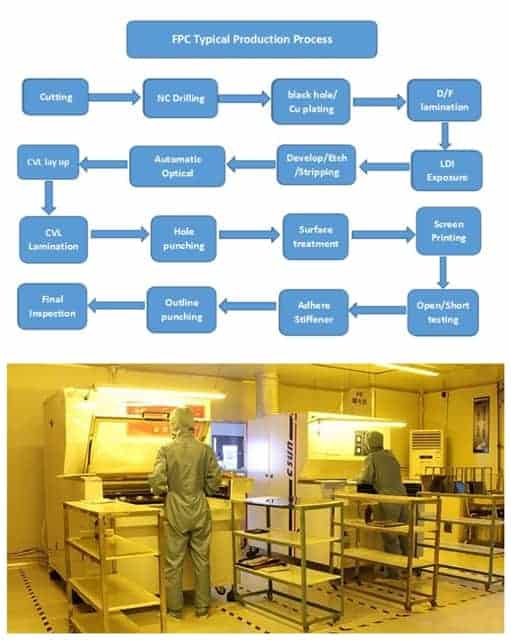
Flexible PCB Production Process
- Single-Sided Boards: Material Cutting → Baking → Dry Film Application → Exposure → Development → Etching → Film Stripping → Pre-treatment → Cover Film Application → Lamination → Curing → Surface Treatment → Electrical Testing → Assembly → Lamination → Curing → Marking → Shaping → Final Inspection → Packaging → Shipping
- Double-Sided Boards: Material Cutting → Baking → Drilling → Black Hole → VCP → Pre-treatment → Dry Film Application → Exposure → Development → Etching → Film Stripping → Pre-treatment → Cover Film Application → Lamination → Curing → Surface Treatment → Electrical Testing → Assembly → Lamination → Curing → Marking → Shaping → Final Inspection → Packaging → Shipping

FPC Applications
In an era where electronic devices continuously strive for miniaturization and multifunctionality, Flexible Printed Circuits (FPC) have become a vital component in a wide array of products due to their unique advantages.
“Flexible Link” in Smartphones:
In the constrained internal space of smartphones, FPC plays a crucial role in connecting the motherboard with components like the display, camera, fingerprint sensor, and more. Its thin and bendable nature not only fits the complex internal structure of the device but also maximizes space efficiency, enabling sleek, lightweight designs and enhancing overall performance.
The Ideal Choice for Wearables:
Wearable devices such as smart bracelets and smartwatches require components that are both flexible and lightweight. FPC can seamlessly conform to the contours of the human wrist, ensuring a comfortable fit while maintaining stable signal transmission inside the device, thus providing users with an enhanced and convenient experience.
Reliable Connectivity in Automotive Electronics:
Automotive electronics are complex, with FPC being used to connect dashboards, sensors, in-car entertainment systems, and more. Its resistance to vibration and impact allows it to withstand the demanding conditions inside a vehicle, ensuring stable communication between electronic devices and supporting both safety and comfort on the road.
From consumer electronics to the automotive sector, FPC continues to push the boundaries of its applications, driving innovation in electronic products across various industries with its lightweight, flexible, and reliable characteristics.
Unveiling FPC Substrate Materials: Characteristics & Comparison
In Flexible Printed Circuit (FPC) manufacturing, the choice of substrate materials plays a critical role in performance. The most commonly used materials are Polyimide (PI) film and Polyester (PET) film.
Polyimide (PI): The High-Performance Choice
Polyimide film is the gold standard in FPC manufacturing, known for its exceptional thermal resistance. It can operate stably from -200°C to +300°C, making it ideal for high-temperature environments, such as electronic connections near automotive engines. PI also offers excellent chemical stability, resisting corrosion from harsh substances, ensuring reliable performance in complex environments. Additionally, its high mechanical strength allows it to endure repeated bending without damage, making it suitable for foldable smartphones and other flexible electronics. However, the higher cost of PI film limits its use in cost-sensitive applications.
Polyester (PET): The Cost-Effective Alternative
PET film is the budget-friendly option, making it ideal for mass production in consumer electronics like headphones and smart wristbands. It provides adequate flexibility for basic bending needs. However, its lower heat resistance makes it unsuitable for SMT assembly or wave soldering, restricting its use to simple plug-in connectors. Additionally, PET has lower dimensional stability, meaning its size can change under variations in temperature and humidity, potentially affecting FPC precision.
Choosing the Right Material
- Polyimide (PI): Best for high-performance, high-reliability applications in demanding environments.

- Polyester (PET): Ideal for cost-sensitive, consumer electronics where extreme durability and heat resistance are not required.

When designing an FPC, selecting the appropriate substrate requires a careful balance between performance, cost, and application needs to ensure optimal results.
Types of Flexible PCB
- Single-Sided Flex PCB
- Structure: Contains a single layer of conductive copper foil bonded to one side of a flexible substrate (polyimide + adhesive). The other side may be covered with a film or exposed.
- Features:
- Lightweight: Very thin and flexible.
- Low Cost: Relatively lower manufacturing costs.
- Simple Design: Suitable for simple circuit designs.
- Double-Sided Flex PCB
- Structure: Features two layers of conductive copper foil on both sides of the flexible substrate, connected through vias. The cover layer is bonded to both sides of a double-sided FPC core with plated through-holes. Reinforcements may or may not be included.
- Features:
- Increased Routing Density: Allows routing on both sides, enhancing circuit density.
- Moderate Cost: Higher manufacturing cost than single-sided boards but lower than multilayer flex boards.
- Moderate Design Complexity: Suitable for moderately complex circuit designs.
- Multilayer Flex PCB
- Structure: Composed of multiple layers of conductive copper foil and flexible substrate, with layers connected via vias to form a complex circuit structure. The cover layer is bonded to both sides of a structure containing three or more conductive layers with plated through-holes. Reinforcements may or may not be included.
- Features:
- High Routing Density: Ideal for complex circuit designs, allowing high-density routing.
- High Design Flexibility: Supports complex 3D routing and multifunctional integration within a limited space.
- High Cost: Higher manufacturing cost, suitable for high-performance applications.
How to Calculate the Bending Radius of Flexible PCB?
The thickness of the flexible PCB directly affects its bending capability. Thinner boards have smaller bending radii. Different materials and circuit designs also influence bending performance. Smaller trace spacing or overly compact layouts may require larger bending radii.
Here are some formulas for specific cases:
- For Single-Sided Flexible Circuit Boards: Minimum Bending Radius Formula: R=(c/2)[(100-EB)/ EB]-D Where:
- R = Minimum bending radius (µm)
- c = Copper foil thickness (µm)
- D= Cover film thickness (µm)
- EB = Copper foil deformation amount, expressed as a percentage.

Maximum copper foil deformation values:
- Rolled copper: ≤ 16%
- Electrolytic copper: ≤ 11%
For different usage scenarios, the deformation values may vary. For one-time bending applications, use the critical limit value (16% for rolled copper). For bending installations, use the minimum deformation value specified by IPC-MF-150 (10% for rolled copper). For dynamic flexible applications, use 0.3%, and for magnetic head applications, use 0.1%. By setting the allowable deformation amount, you can calculate the minimum bending radius.
For specific customization and requirements, please contact Greatpcb. Our technical team will carefully review your needs and provide timely feedback.
The thickness of the flexible PCB directly affects its bending capability. Thinner boards have smaller bending radii. Different materials and circuit designs also influence bending performance. Smaller trace spacing or overly compact layouts may require larger bending radii.
Here are some formulas for specific cases:
- For Single-Sided Flexible Circuit Boards: Minimum Bending Radius Formula: R=c2[100−EBEB]−DR = frac{c}{2} left[frac{100 – EB}{EB}right] – D Where:
- RR = Minimum bending radius (µm)
- cc = Copper foil thickness (µm)
- DD = Cover film thickness (µm)
- EBEB = Copper foil deformation amount, expressed as a percentage.
Maximum copper foil deformation values:
- Rolled copper: ≤ 16%
- Electrolytic copper: ≤ 11%
For different usage scenarios, the deformation values may vary. For one-time bending applications, use the critical limit value (16% for rolled copper). For bending installations, use the minimum deformation value specified by IPC-MF-150 (10% for rolled copper). For dynamic flexible applications, use 0.3%, and for magnetic head applications, use 0.1%. By setting the allowable deformation amount, you can calculate the minimum bending radius.
For specific customization and requirements, please contact Greatpcb. Our technical team will carefully review your needs and provide timely feedback.
FPC Manufacturer
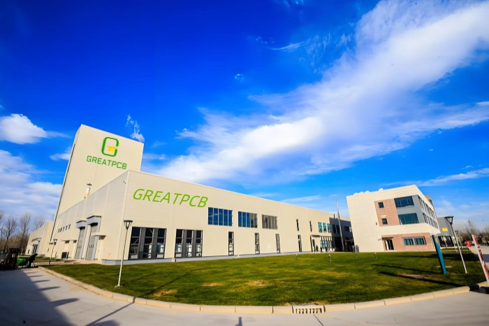
Greatpcb is a professional flexible PCB and FPC assembly manufacturer with over 15 years of experience. We offer one-stop services from flexible PCB production to assembly. Equipped with advanced automated production equipment, we also support rigid-flex PCB and flexible PCB prototyping.


