


Connect rigid circuit sections with flexible layers in one integrated board. Fit electronics into compact enclosures and reduce separate cables and connectors.
GreatPCB provides rigid-flex PCB fabrication and assembly services. Send your design files to discuss the board construction, quantity and delivery requirements.
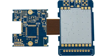
Rigid circuit sections joined by a flexible connection. Illustrative third-party board.
Why Rigid-Flex?
Fit More Into Less Space
Fold the flexible sections to place rigid boards on different planes. This helps fit circuitry around the shape of a compact enclosure.
Reduce Connectors and Cables
Continuous flexible circuits link the rigid sections. Fewer separate interconnects mean fewer parts to purchase, install and inspect.
Simplify Installation
Handle connected circuit sections as one assembly rather than routing separate cables between boards. This can make installation more straightforward in tightly packed products.
What Is a Rigid-Flex PCB?
A rigid-flex PCB combines rigid board sections and flexible circuit layers in a single structure. The rigid areas support components; the flexible areas connect them and accommodate the installed shape.
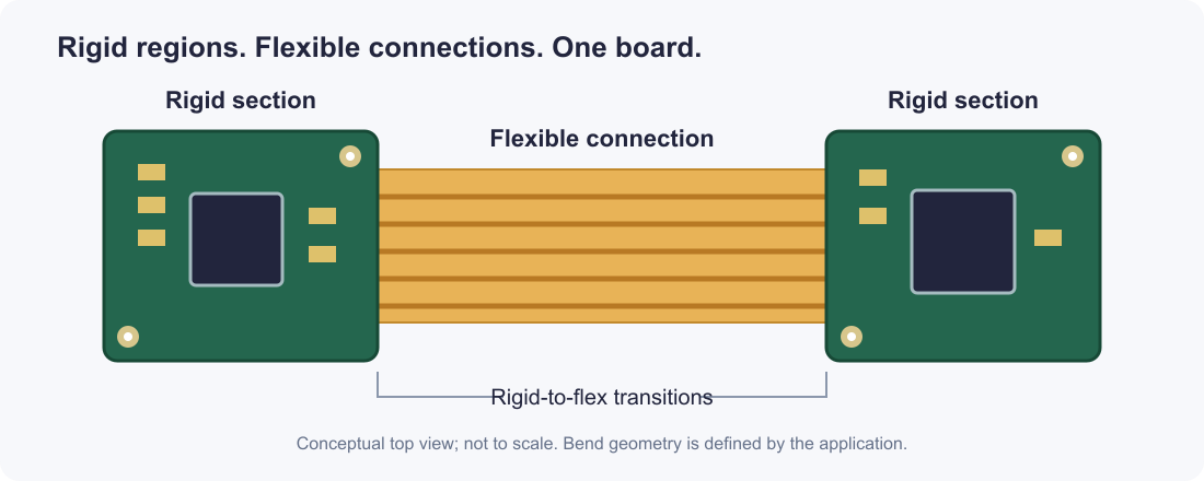
Conceptual construction: rigid sections and flexible connections form one circuit.
Rigid Sections
Provide a stable base for components, connectors and mounting points.
Flexible Connections
Carry circuits between rigid sections and allow the assembly to fold into its housing.
One Integrated Board
Flexible circuit layers continue into the rigid regions. A flex PCB with a stiffener adds mechanical support, but does not create the same interconnected rigid-layer structure.
Manufacturing Options
GreatPCB offers PCB fabrication and assembly in one service. For rigid-flex projects, the construction brings together the rigid circuit areas, flexible connections and their protective layers.
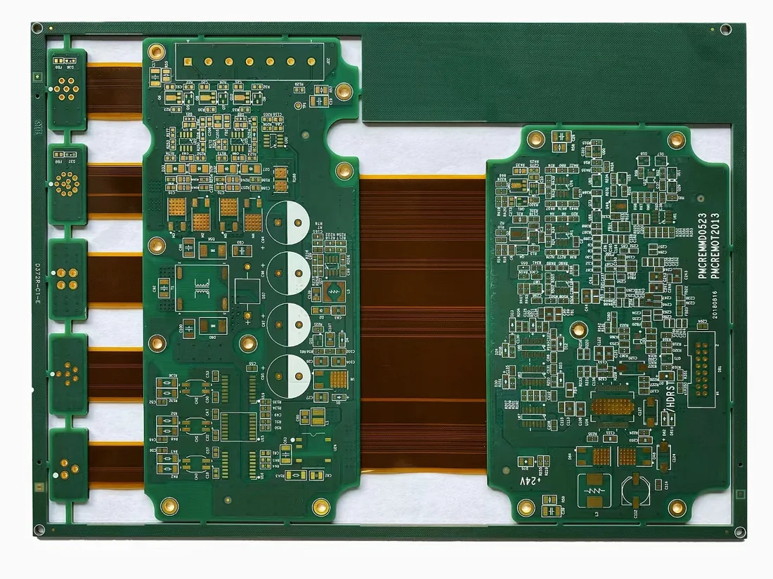
Example of rigid and flexible regions arranged within a manufacturing panel.
Applications
Rigid-flex is especially useful when boards must fit around a housing or connect across different planes.
Medical and Handheld Devices
Fit circuit sections around displays, batteries and mechanical parts in a compact instrument.
Wearables and Consumer Electronics
Connect small circuit areas while reducing the space occupied by separate connectors and cables.
Industrial and Communications Equipment
Link circuit sections positioned around mounting points, interfaces and enclosure features.
Aerospace and Defense Electronics
Address packaging, weight and interconnection constraints. Inspection and qualification requirements follow the specific project.
Design Essentials
Define How the Board Bends
State whether the flex section is folded during installation or moves repeatedly in use. Bend life depends on the flex construction and motion; folding once does not prove repeated-bend durability.
Protect the Transition
Allow free flex length between rigid edges. Keep components and plated holes clear of the active bend, and review the transition geometry with the fabricator.
Show the Installed Shape
A flat outline shows how to manufacture the board. A formed drawing shows how it must fit. Providing both helps identify tight bends and mechanical interference before production.
For detailed bend calculations and layout examples, read our Rigid-Flex PCB Bend Radius Guide.
From Files to Finished Boards
1. Review the Design
Define the rigid and flex regions, stackup, materials and critical dimensions.
2. Build the Circuit
Form the flexible circuitry, add its protection and laminate the rigid regions according to the construction.
3. Complete Fabrication
Form and plate the required holes, complete outer circuits, apply the surface finish and release the board outline.
4. Inspect and Deliver
Check the boards against the agreed requirements. Include assembly in the order when required.
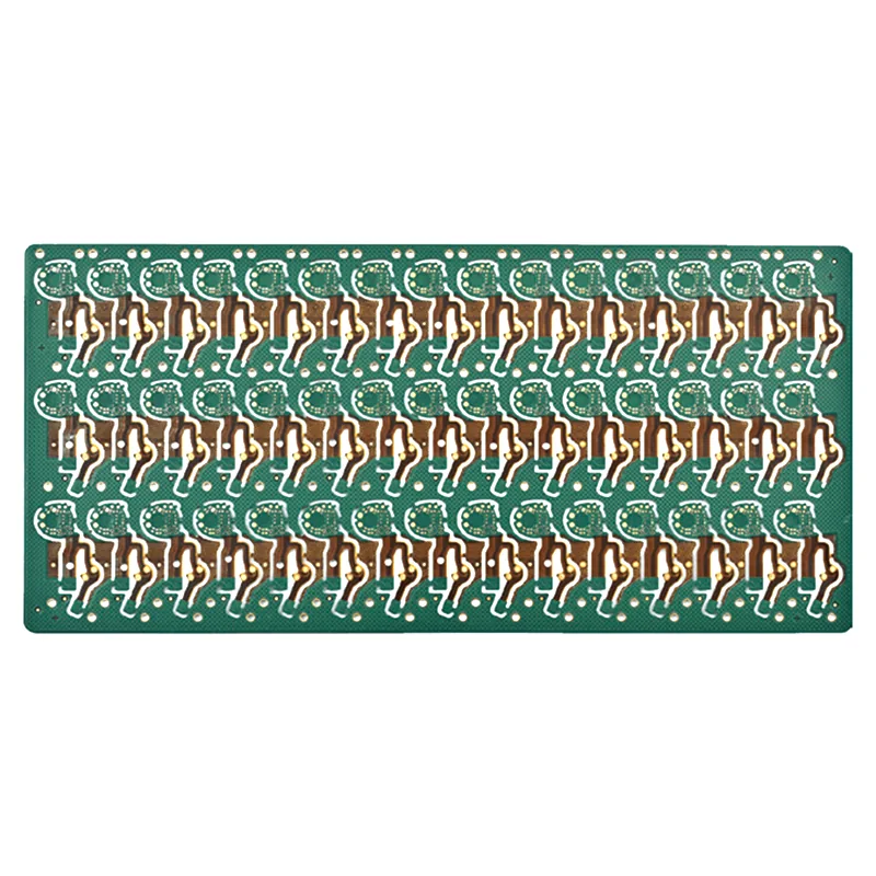
Repeated board outlines arranged in a manufacturing panel.
Quality and Testing
Circuit Connections
Electrical continuity and isolation checks help identify open circuits and shorts.
Construction and Dimensions
Review rigid and flex thicknesses, critical dimensions, coverlay openings, transitions and flex edges.
Project-Specific Verification
Specify impedance reports, cross-sections or reliability testing when required. Electrical testing alone does not establish bending life.
Get a Rigid-Flex PCB Quote
Send your Gerber and drill files, stackup and board drawing, together with the quantity and delivery target. Include a formed drawing and bending requirements; add assembly files if needed.
Rigid-flex boards can cost more to fabricate than rigid boards. Compare the complete assembly—including the cables, connectors and installation work the design can replace. Construction, panel layout, materials and testing also affect cost and lead time.
FAQs
Is rigid-flex the same as a flex PCB with stiffeners?
No. A stiffener reinforces a flex circuit mechanically. Rigid-flex integrates electrically connected rigid circuit layers with flexible layers in one board.
Can the flexible section bend repeatedly?
It can be designed for repeated motion, but that requirement must be defined early. Materials, flex thickness, bend geometry and validation must suit the intended use.
Why does rigid-flex cost more than a rigid PCB?
It combines different materials and adds processing for alignment, lamination and flex protection. Layer count, flat panel layout, quantity and inspection requirements also affect the quote.
Can I include PCB assembly in the quote?
Yes. Add the BOM, component placement data and assembly drawing to your fabrication files, and identify any functional testing requirements.