
Assembly


PCB Assembly Component Shortages: What to Do When a Part Is Unavailable
Why Is There Too Much Solder Paste? Stencil Thickness, Apertures and Printing Checks
PCB Footprint Mistakes: How to Check Pinouts and Dimensions Before Ordering
FLEXIBLE CIRCUITS · ASSEMBLY
GreatPCB provides flex PCB assembly for prototype and production projects, with flexible circuit fabrication, component sourcing, SMT assembly and testing coordinated around your design. Share your Gerber files, BOM and assembly drawings so we can review the board construction, component requirements and finished shape before preparing a quotation.
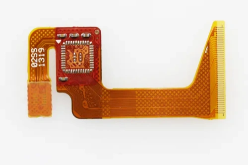
A flexible circuit with a component region and connector tail.
Flexible PCB assembly mounts and solders components onto a flexible printed circuit, often called an FPC. The flexible sections let a circuit fit a compact enclosure or connect moving parts; the component areas need suitable support during assembly and in the finished product.
Flex PCB Assembly Options
The assembly approach starts with where the components sit and how the circuit will be used. A board folded once during installation has different mechanical requirements from a circuit that moves repeatedly in service.
| Circuit construction | Assembly considerations |
|---|---|
| Flexible circuit | Support the thin substrate during printing, placement and soldering, while keeping the intended bend areas free to move. |
| Flexible circuit with local stiffeners | Reinforce selected areas, such as connectors or component mounting regions. Confirm the stiffener outline, thickness, adhesive and attachment requirements. |
| Rigid-flex circuit | Mount components in the designated assembly regions and review the flexible sections, transitions and finished geometry together. |
A stiffener adds mechanical support to a flexible circuit. A rigid-flex PCB combines rigid and flexible circuit sections within its construction. This distinction matters when reviewing stackup, tooling and assembly access.
Projects can involve SMT components, specified through-hole connectors and additional wire or cable connections. Single- and double-sided layouts need different support arrangements, so both sides of the assembly drawing should be available for review.
For turnkey projects, GreatPCB can coordinate board fabrication, component purchasing and assembly. If you already have the flexible boards or selected components, identify what you will supply and what you need us to source. This keeps the quotation and material responsibilities clear.

Rigid circuit regions and flexible links within a manufacturing panel, before component assembly.
Design Review Before Assembly
A successful flex assembly depends on the relationship between the flat circuit, its component locations and the shape it takes inside your product. Reviewing these together helps identify problems before tooling or material purchasing begins.
Bend Zones and Component Locations
Mark the intended bend areas and show whether the circuit will remain fixed or move during use. Component bodies, solder joints and connector attachments need protection from the stresses created by that movement.
For example, a connector can solder correctly while the board is held flat, yet leave its pads exposed to mechanical load when a cable is inserted. Reviewing its local support and the nearby bend location addresses a different problem from checking the solder joint alone.
Use an assembly or mechanical drawing to show bend direction, mounting points and the finished shape. For designs that move repeatedly, include the movement range and required validation conditions. The appropriate bend geometry depends on the circuit construction and application.
Stiffeners, Panels and Carrier Tooling
Permanent stiffeners support the finished circuit. They can reinforce a connector, component region or contact area. Their material and attachment method must fit the design and manufacturing sequence.
Temporary carriers support the manufacturing process. A carrier or fixture holds the flexible circuit flat and provides repeatable positioning. Without adequate support, printing pressure or placement force can move the substrate and affect solder paste deposition or component positioning.
Panel outlines, tooling holes and fiducial marks should be reviewed with that support arrangement. In a double-sided build, the tooling also needs to accommodate components already fitted to the first side. Share component heights and any restrictions on where a fixture can contact the board.
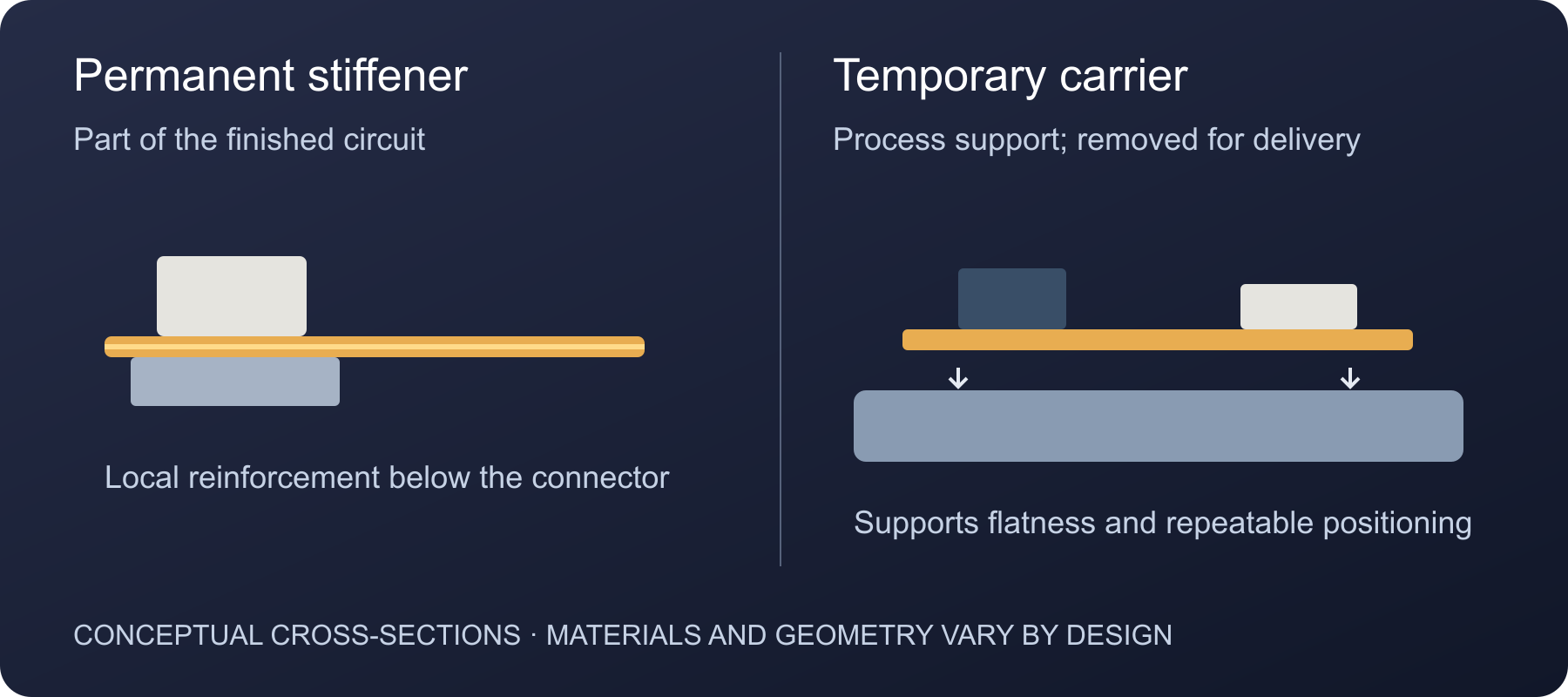
Permanent stiffeners and temporary carriers solve different support needs. Conceptual views, not to scale.
Coverlay, Materials and Thermal Limits
Coverlay protects the flexible circuit while leaving defined areas exposed for soldering or connection. Its openings, pad layout and nearby stiffeners should be reviewed together, particularly around connectors and closely spaced components.
The material specification also affects assembly planning. Base film, adhesives, stiffeners, surface finish and components must be compatible with the selected soldering process. Storage history and the supplier’s handling instructions help determine whether drying or other preparation is needed.
Provide the actual stackup and material requirements wherever possible. A description such as “flexible PCB” alone does not establish an appropriate reflow profile or baking condition.
Flex PCB Assembly Process
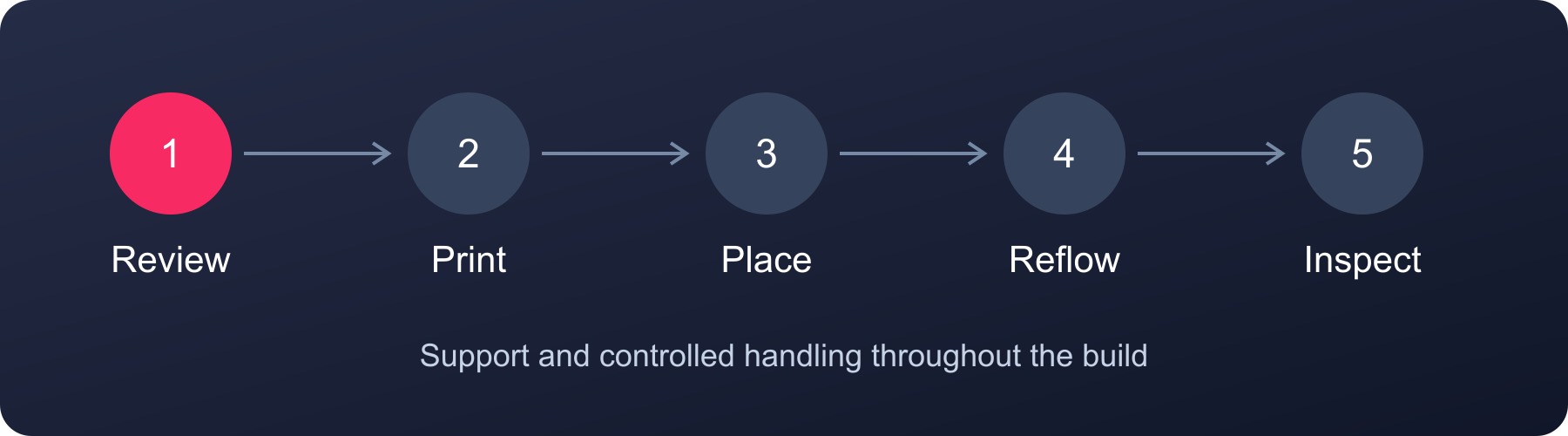
A typical assembly sequence. Additional operations depend on the project.
Flex circuit assembly follows the familiar progression of preparation, component placement, soldering and inspection, with support and handling planned for the flexible construction.
1. Confirm Files, Materials and Support
Review the released BOM, placement data, assembly drawings and mechanical requirements. Check incoming boards and components against the approved build information, then prepare the support tooling and any material conditioning required by the selected materials.
Permanent stiffener attachment belongs at the stage specified for the construction and adhesive system. It should be planned before production rather than treated as an automatic finishing step.
2. Print Solder Paste and Place Components
Secure the circuit on suitable support, align the stencil and print solder paste onto the exposed pads. Stable support helps maintain consistent contact during printing and gives the placement system a repeatable board position.
The placement setup must account for the circuit outline, component orientation and local support. Where solder paste inspection is included, it checks the printed deposits before the board proceeds to soldering.
3. Reflow the Supported Assembly
Develop the reflow conditions around the chosen solder paste, component limits and complete board construction. The carrier is part of this assessment because it can affect how the assembly heats and cools.
The aim is to form the required solder joints while keeping the circuit and components within their permitted processing conditions. Flexible construction does not, by itself, require a particular low-temperature solder or a universal peak temperature.
4. Complete Specified Additional Operations
Add connectors, through-hole parts, wires or other attachments in the planned sequence. The support needed for these operations depends on the joint locations and access around nearby components.
Cleaning, conformal coating or local protective materials can be included where the product requires them. Define coating areas and exclusions, especially around contacts, connectors and moving regions, so the treatment fits the circuit’s intended use.
5. Inspect and Release for Delivery
Complete the agreed inspections and tests, then release the assembly from its tooling using a handling method suited to its construction. Confirm whether the boards should be delivered flat or in a specified formed condition before selecting packaging.
Inspection, Testing and Handling
The inspection plan should connect each check to a defined assembly risk.
- Optical inspection assesses visible component placement, orientation and accessible solder joints within the programmed inspection coverage.
- X-ray inspection can be evaluated for applicable hidden solder joints, such as those beneath BGA packages.
- Electrical testing checks the connections or circuit parameters covered by the selected test method and available test access.
- Functional testing exercises the operating functions defined in the test plan. Provide the required power conditions, firmware, test procedure and acceptance criteria where applicable.
Bare-board electrical testing takes place before components are fitted. The completed assembly needs its own agreed verification plan, covering the relevant soldering, electrical and operating requirements.
Mechanical validation has its own purpose. If a circuit must survive repeated movement, define the bend arrangement, movement and acceptance requirements for that evaluation. A visual inspection or a board function check alone does not establish a flex-cycle lifetime.
Handling and packaging should protect both the assembly and its flexible sections. Support connectors and populated areas, avoid unintended creases, and keep the agreed delivery shape. Include any restrictions on folding or forming in the drawings and packaging instructions.
What Affects Cost and Lead Time?
Flex PCB assembly cost reflects the preparation work as well as the number of boards being built.
Tooling and setup: Circuit shape, panel layout and component locations determine the support needed during assembly. New carrier tooling or test fixtures may introduce a one-time preparation cost.
Assembly complexity: A second populated side, additional connector operations, local stiffeners or specified coating can add handling and process steps.
Material availability: The board construction and BOM affect procurement. Identify approved component alternatives and customer-supplied parts before confirming the build schedule.
Testing and delivery requirements: Programming, functional test fixtures, mechanical validation and special packaging require their own preparation and acceptance details.
Send the intended build quantity and your required delivery date with the project files. We can then discuss the assembly scope and outstanding inputs. For a broader explanation of quotation items, see PCB assembly cost.
What to Prepare for Flex PCB Assembly
The most useful file set describes both the circuit in its flat state and how it will sit inside the finished product.
| File or requirement | Information to include |
|---|---|
| PCB fabrication data | Gerber and drill files, stackup, material specification, surface finish and any controlled board requirements. |
| BOM and supply arrangement | Manufacturer part numbers, quantities, reference designators, approved alternatives and which parts you will supply. |
| Placement data and assembly drawings | Component coordinates, rotation, board side, polarity, connector orientation and special assembly notes. |
| Flex construction details | Coverlay openings, stiffener material and location, attachment requirements, panel information and tooling features. |
| Mechanical and bend information | Bend areas, fixed and moving regions, mounting points, finished geometry and component clearance. A dimensioned drawing may be sufficient; include a 3D model when it helps explain the assembly. |
| Validation and delivery requirements | Programming files, test procedures, acceptance criteria, required records and whether delivery should be flat or formed. |
If your project is still being finalized, identify the unresolved items and send the latest revision. This lets the review focus on the decisions that affect assembly, tooling and quotation.
Have a flexible circuit project to review? Send your files, build quantity and finished-shape requirements to discuss the next steps with GreatPCB.
FAQs
Can a flex PCB have components on both sides?
Yes. The design and process need to allow support through both assembly sequences. Component height, underside clearance, tooling contact areas and thermal exposure should be reviewed before committing to the layout.
Does flex PCB assembly require low-temperature solder?
The soldering process is selected for the complete assembly. The solder alloy, components, base material, adhesives and support tooling all matter. A suitable profile should be established for that combination rather than chosen solely because the board is flexible.
Can I supply the flexible boards or components?
You can submit a project with customer-supplied boards or selected components for review. Include the board specification, packing list, part quantities and relevant storage or handling information so we can confirm the supply arrangement and remaining sourcing work.