
Technical
Assembly
Technical
Assembly
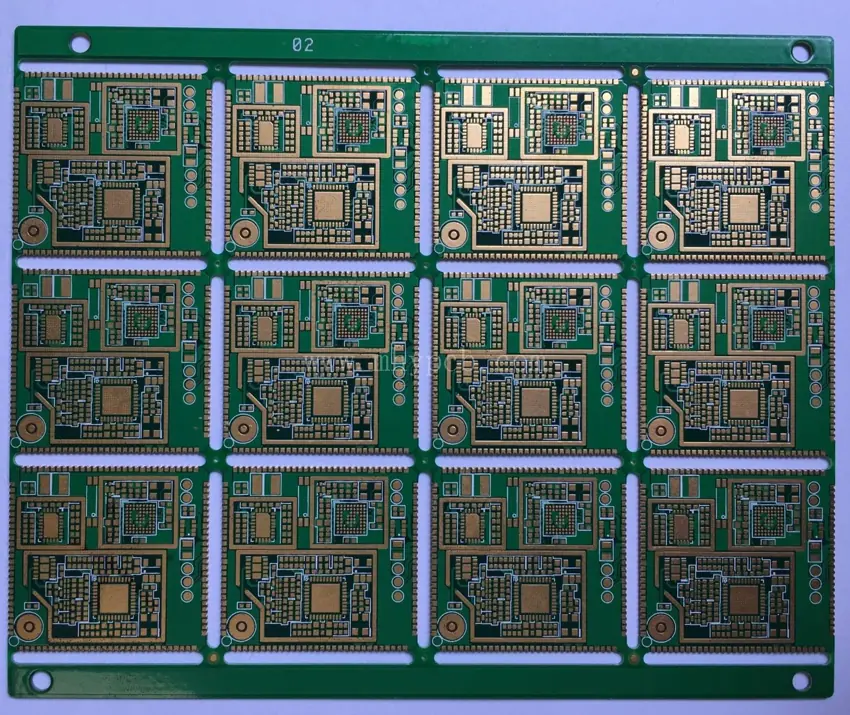
Small boards, irregular outlines and components close to the edge can make a PCB difficult to handle on an assembly line. Panelization brings one or more boards together in an array, with the support and reference features needed for the agreed manufacturing and assembly process.
At GreatPCB, we can review a customer-provided panel layout or discuss a suitable arrangement for the project. Board shape, material, assembly equipment and the way the finished boards will be separated all influence the design.
What Is a PCB Assembly Panel?
An assembly panel is a group of connected circuit boards handled as one unit during production. The individual boards remain attached through assembly and are separated at the appropriate stage.
An assembly panel is not necessarily the same size as the larger fabrication panel used to manufacture the boards. A layout that fits a fabrication process also needs to fit the assembly line, inspection and depaneling method.
Depending on the project, a panel may include:
- PCB units: repeated boards or, where suitable, different board designs.
- Process rails: removable material that provides space for handling or reference features.
- Connections: V-scores or routed tabs that hold the array together until separation.
- Panel references: fiducial marks and tooling holes where required by the assembly process.
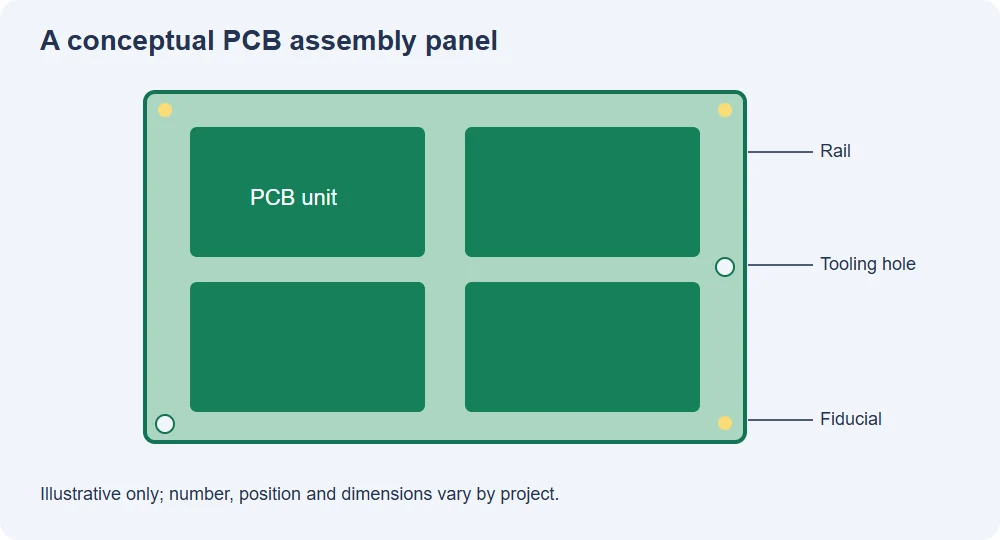
Conceptual panel layout. Positions and dimensions depend on the project.
What Should Be Considered Before Panelizing a PCB?
Before choosing a layout, look beyond how many boards fit in an array. The panel needs to remain stable from fabrication through assembly, inspection and separation.
| Consideration | Why it matters |
|---|---|
| Board and panel size | The array must be compatible with the relevant production equipment and handling method. |
| Board thickness and material | Thin or flexible boards may need extra support during transport or assembly. |
| Component locations | Parts near the edge or overhanging the board can affect rail and tab placement. |
| Board outline | Curves, slots and irregular shapes influence the connection method. |
| Separation and finished edge | The chosen method must suit nearby copper, components and the enclosure fit. |
| Delivery format | Decide whether the project needs individual boards or assembled panels. |
The most compact arrangement is not always the easiest to assemble. Board spacing, rails and support must also leave enough room for the production process.
V-Cut, Tab Routing or a Combination?
The connection between boards determines how the panel stays together and how each unit is removed. The choice depends on the board outline, production equipment and the finished edge requirements.
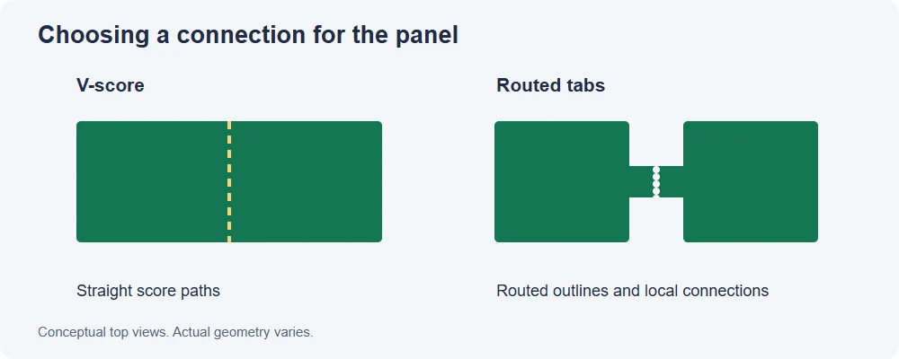
Two common panel connections, shown as top views. Not to scale.
V-Cut / V-Score
V-cut forms straight grooves in the panel, commonly on both sides of the board. Material remains between the grooves to hold the panel together until depaneling.
V-scoring is often a practical option when board edges and the panel arrangement allow straight scoring paths. The remaining material, copper clearance and distance from nearby components need to suit the board and the separation method.
A score line may need to continue across the panel, depending on the fabricator’s equipment. If that line would cross another board or an important feature, the layout or connection method may need to change.
Routed Tabs With Breakaway Holes
For a routed outline, small tabs can connect the board to another unit or a rail. A row of holes in the tab creates a weakened area for separation; these perforations are often called mouse bites.
This method can accommodate curves and irregular outlines, but it also leaves specific tab locations to separate and inspect. Tab position, hole geometry, panel support and the acceptable finished edge should be reviewed together.
Our PCB mouse bites guide explains how hole diameter, pitch and the remaining material between holes relate to each other.
Routed Tabs Without Breakaway Holes
Some routed panels use narrow material connections without a row of holes. The tabs need to hold the array during production and be compatible with the intended cutting or routing operation afterward.
Consider where any remaining tab material will sit on the finished outline, particularly near connectors, enclosure surfaces or other edge features. The width and placement should be agreed for the actual board and process.
Combining V-Cut and Routed Tabs
A panel can combine scoring and routed connections when the layout and manufacturer’s equipment support it. For example, a straight separation may be scored while an irregular section uses routed tabs.
The combined layout still needs enough support throughout assembly, and the score paths must not cut through adjacent boards. Review the complete array rather than treating each connection in isolation.
Panel Size, Board Spacing and Process Rails
Choose a Panel That Fits the Process
The finished array needs to fit the manufacturing and assembly equipment used for the project. Its suitability depends on more than overall length and width: board thickness, rigidity, component height, rail geometry and the direction of travel can also matter.

For unusually small, large, thin or flexible designs, discuss handling and support before finalizing the layout. A carrier may be appropriate for some assemblies, but the arrangement depends on the board and production process.
Leave Room Between Boards
Spacing is affected by the selected score or route, tool access, component overhang and the finished board outline. A routed profile needs room for the intended routing path; a scored layout needs suitable clearance around the score.
Check that a part extending beyond one board will not interfere with a neighboring board, rail, fixture or depaneling tool. The required distance should be confirmed for the actual geometry and equipment.
Use Rails Where Handling Requires Them
Process rails provide additional material around an array. They can create a handling surface and a place for panel-level fiducials or tooling holes without occupying the finished board.
Rails are usually removed later, so their connection points and removal method should be planned with the rest of the panel. Rail width and the clear area needed for conveyors or clamps depend on the production line.
Fiducial Marks and Tooling Holes
Fiducial marks and tooling holes help different equipment locate or hold the panel. They are related, but they do different jobs.
Panel Fiducial Marks
Fiducials are visible reference features used by machine vision to locate and orient a board or panel. A panel may use global marks, while individual boards or fine-pitch components may also need their own references, depending on the assembly plan.
Keep the marks visible to the equipment, with a suitable surface finish and clear area around them. Rail placement, solder-mask opening and surrounding features all affect recognition. See our PCB fiducial marks guide for the relationship between the copper mark, mask opening and clearance.
Tooling Holes
Tooling holes are mechanical features that can help align or secure a panel in a fixture or process. Their need, size and position depend on the equipment and fixture design.
Make sure holes do not conflict with rails, score paths, nearby copper or finished-board features. Confirm the required hole type and tolerances with the manufacturing team.
Protect the Board During Assembly and Depaneling
A panel must be strong enough for handling, but the connections must also allow the boards to be separated without unacceptable damage. A weak panel may flex or move during transport; a connection that is difficult to remove can place stress on the finished board.
Pay particular attention to:
- Thin boards or heavy components: consider support during transport, reflow and handling.
- Ceramic components and sensitive solder joints near the edge: review the distance to score lines and tabs, as well as the planned separation method.
- Copper, vias and plated edges: check the route, perforations and final board edge together.
- Connectors and overhanging parts: allow access for the depaneling equipment and the finished enclosure.
- Finished-edge quality: define whether a visible tab remnant or additional finishing is acceptable.
Panel design is a balance of material use, support and separation. The right combination is specific to the board rather than a single rule for every project.
Frequently Asked Questions
Can GreatPCB review my existing panel design?
Yes. You can provide your proposed arrangement for review or discuss the panel layout with our team. The final approach depends on the design and agreed production requirements.
Do all PCB designs need process rails?
Not necessarily. Rails are useful when the panel needs handling surfaces, support or space for reference features. The decision depends on board geometry and the equipment used.
Can different PCB designs be combined on one panel?
Mixed designs can be considered when the construction and production requirements are compatible. Review materials, thickness, surface finish, quantities, orientation and the assembly process before deciding.
Can a panel use both V-cut and mouse bites?
Yes, when the proposed combination is supported by the manufacturing process. Check the score path, routed sections, panel strength and separation sequence together.
Are tooling holes and fiducial marks the same?
No. Fiducials provide visual references for equipment; tooling holes can be used for mechanical alignment or fixture location. A project may need either or both, depending on the process.
Need Help With Your PCB Panel Design?
Share your project requirements with GreatPCB, and we can review the panel layout and assembly needs with you.