
CONTROL. POWER. INSTRUMENTATION.
Industrial PCB Manufacturing & Assembly
GreatPCB provides PCB fabrication and assembly for industrial control, automation, power and instrumentation projects. Bring your board files, BOM and build requirements to discuss fabrication, component sourcing, SMT and through-hole assembly, programming, testing and box build.
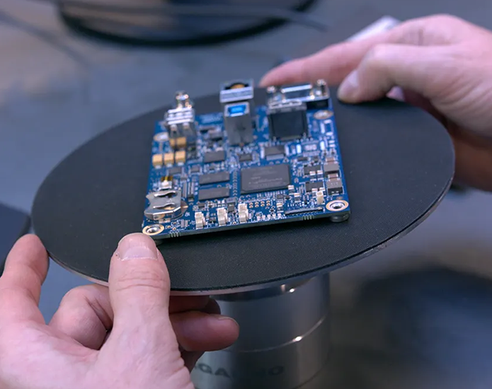
YOUR APPLICATION SETS THE REQUIREMENTS
An industrial control board in a cabinet and a motor-drive board beside a heat source face different demands. We work from your design and project requirements to define the manufacturing scope, inspection needs and delivery requirements for prototypes and repeat orders.
Industrial Applications
Automation & Control
PLC modules, I/O boards, HMI controllers and machine-control electronics connect logic with equipment on the factory floor. Industrial control PCB assembly can involve dense surface-mount circuitry alongside relays, terminal blocks and through-hole connectors. Both the electrical design and the physical assembly need attention.
Motion & Power
Motor controllers, drives and power-conversion boards combine switching devices, current paths and control circuits. Manufacturing requirements depend on the load, heat flow, isolation and mechanical arrangement. Heavy copper may help a particular current path, but it is one part of the design decision.
Monitoring & Instrumentation
Sensor interfaces, data-acquisition boards and process instruments must preserve useful signals in their operating environment. Low-level measurements may need particular attention to contamination, grounding and separation from switching power circuits. Functional checks should reflect the signals the board will actually measure.
| Application | Conditions to identify | Manufacturing discussion |
|---|---|---|
| Automation and control | Connector loading, mixed components, cabinet installation | Assembly sequence, mechanical support and I/O checks |
| Motion and power | Current, switching heat, voltage and cooling | Copper construction, soldering requirements and test loads |
| Monitoring and instrumentation | Sensitive inputs, humidity and nearby noise sources | Cleanliness, protection and measurement limits |
PCB Manufacturing & Assembly
PCB Fabrication
The fabrication specification defines the laminate, layer stackup, copper requirements, holes, surface finish and dimensional requirements. State these in the board files and fabrication drawing so the quotation and production data describe the same construction.
If the design calls for heavy copper PCB manufacturing, identify the required layers and finished copper thickness. Thicker conductors affect fabrication as well as current handling; trace geometry and spacing still need review.
Component Sourcing & Assembly
For component sourcing, provide manufacturer part numbers, quantities and approved alternatives. Similar package names or headline specifications do not establish that two parts are interchangeable. Electrical, thermal, firmware and mechanical differences may require customer approval before substitution.
SMT assembly brings together solder-paste printing, placement, reflow and inspection. Through-hole parts may require additional soldering operations. Large connectors, relays and heat-sensitive devices can affect the assembly sequence, while component handling requirements and the board’s thermal response influence process preparation.
Programming & Integration
Where the project includes IC programming, identify the device, released firmware, programming interface and verification method. Include any required serial-number or configuration data and instructions for handling it.
For box build assembly, add enclosure drawings, cable information and final assembly instructions. Define whether the deliverable is a populated board, a programmed and tested assembly, or an integrated unit before production begins.
Materials & Design Requirements
Heat & Current
Choose materials from the board’s operating conditions and manufacturing needs. Tg describes a glass transition in the resin system; it does not, by itself, specify the continuous operating temperature of a complete assembly. Component ratings, laminate properties and the thermal design must also suit the application.
Copper thickness, conductor width, layer allocation and cooling work together. A short high-current path and a densely routed control section may need different treatment on the same board. Provide the expected loads and available cooling so fabrication choices can be reviewed against the design.
Mechanical & Environmental Conditions
Mounting points, board dimensions, connector forces and component height affect how the assembly fits and survives handling. Equipment exposed to vibration may also need defined support for heavier parts and cables. Include these details in the mechanical and assembly drawings.
Humidity, condensation, dust and chemical exposure create different protection needs. State what the board encounters inside its enclosure, including start-up and shutdown conditions. Conformal coating may be appropriate, but its material, coverage and compatibility need to match that exposure.
Signal Integrity & Isolation
Industrial boards often place sensitive sensing circuits near processors, communication interfaces and switching power stages. The design needs suitable routing, return paths, separation and insulation for those functions. Manufacturing review can identify conflicts between the supplied layout and fabrication or assembly requirements.
Provide specified impedance, insulation distances and any applicable safety requirements. There is no single spacing rule for every industrial PCB: the required separation depends on the electrical conditions, environment and governing design requirements.
| Working condition | What needs review | Useful project input |
|---|---|---|
| Sustained load or nearby heat | Materials, copper paths and heat removal | Load profile, temperatures and cooling arrangement |
| Vibration or frequent connection | Mounting, connector retention and heavy parts | Mechanical drawings and assembly constraints |
| Moisture or contamination | Cleanliness, coating and exposed interfaces | Environment description and coating drawing |
| Sensitive signals or isolated circuits | Routing constraints, separation and verification | Electrical requirements and test limits |
Inspection, Testing & Protection
Bare-Board & Assembly Checks
Bare-board electrical testing checks connectivity against the test data. Assembly inspection addresses different questions: solder-paste inspection examines deposited paste, AOI checks visible assembly features, and X-ray can help assess otherwise hidden solder connections. The appropriate methods depend on the components and inspection requirements.
Each method has limits. A hidden joint may require a particular viewing approach, and an acceptable image does not demonstrate that the board performs its intended function. Define the inspection scope and acceptance criteria for the build rather than assuming one method covers every defect.
Functional & Environmental Testing
A functional test needs a defined procedure: how to power the board, what inputs to apply, which outputs to measure and what constitutes a pass. Firmware, test fixtures, loads and communication tools may all be part of that setup. Our assembly testing information explains the available approaches to discuss for your project.
Environmental or reliability testing requires a separate plan. Specify the conditions, sample size, sequence and acceptance limits, and confirm responsibility for execution and reporting. Testing an assembly under an agreed program does not establish a fixed service life for every installation.
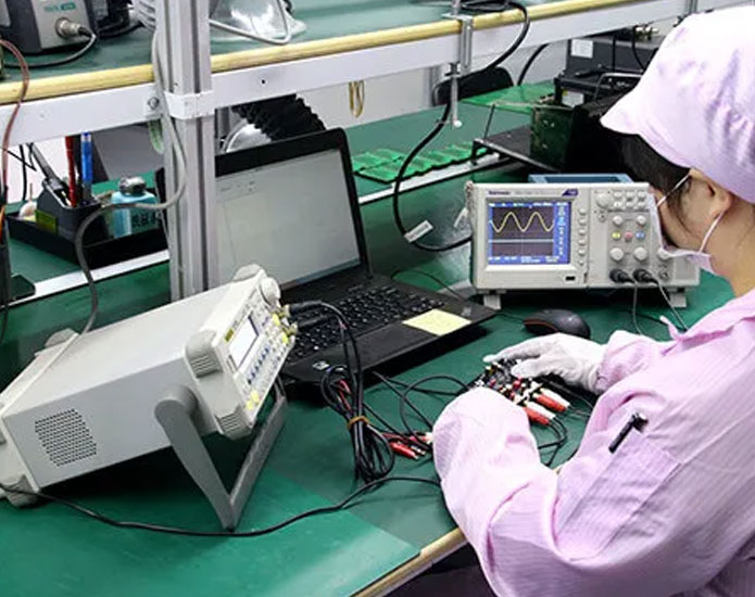
A functional check needs defined inputs, measurements and pass limits.
Cleaning & Conformal Coating
Cleaning requirements depend on the residue, component compatibility and operating environment. Moisture and ionic contamination can contribute to leakage or electrochemical migration under electrical bias. A board that looks clean may still require further assessment, particularly for sensitive circuits or subsequent coating.
Conformal coating needs a controlled sequence:
- Prepare the assembly. Complete the agreed checks required before coating, and clean and dry the board using a compatible process.
- Define protected and exposed areas. Use the coating drawing to identify coverage and masking for contacts, connectors, test access and other required surfaces.
- Apply and cure the material. Follow the selected coating’s requirements for application, film thickness and cure, together with component restrictions.
- Inspect the result. Check coverage, masked areas and defects such as bubbles, pinholes or unwanted deposits; complete any specified checks after coating.
“No-clean” flux does not settle every coating decision. Residue compatibility still matters, and coating over unsuitable contamination can create adhesion or electrical problems. Coating also does not make the finished equipment waterproof; protection depends on the board, enclosure and exposure together.
Prototype to Repeat Production
First Builds
Use the first build to check that the released files, purchased parts, assembly instructions and test setup work together. Resolve discrepancies before carrying them into the next batch. Record approved corrections in the production documents so later orders can use the same agreed baseline.
If the project begins with low-volume PCB assembly, share the expected next stage as well as the immediate quantity. A prototype for electrical evaluation may need different preparation from a pilot run used to establish the repeat-build process.
Repeat Orders & Changes
A repeat order needs more than the previous purchase-order number. Confirm the hardware and BOM revision, approved parts, firmware and test requirements. A component change can affect stocked material, boards already being assembled and future production, so its effective point must be clear.
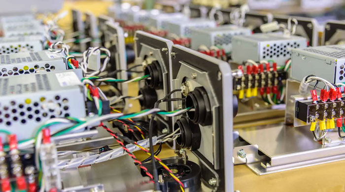
Repeat builds need consistent board, component and integration instructions.
| Establish for the first build | Confirm when something changes |
|---|---|
| Released PCB, BOM and assembly files | New revisions and the batch where they take effect |
| Approved parts and alternatives | Approval and verification of substitutions |
| Firmware and test procedure | Updated programs, fixtures and pass limits |
| Required build and inspection records | Treatment of affected stock and work in progress |
Agree the traceability detail you need to retrieve later—for example, the board revision, component lot or test result. Record requirements should answer those questions without assuming every project needs the same tracking system.
Project Requirements
Send the files available for your current stage. For a manufacturing quotation, the starting package normally includes:
- PCB data: Gerber and drill files, fabrication drawing, stackup, material, copper, finish and dimensional requirements.
- Assembly data: BOM with manufacturer part numbers, placement data and assembly drawings, including polarity and special instructions.
- Build plan: quantity, prototype or repeat-order status, required delivery date and any staged deliveries.
Add the following where relevant:
- Operating conditions, mechanical constraints and specified acceptance requirements.
- Firmware, programming instructions, test procedures, fixtures and pass/fail limits.
- Cleaning or coating requirements, coverage and masking drawings.
- Enclosure and cable information, packaging instructions and required traceability records.
Discuss Your Industrial PCB Project
Share your files and the intended application with GreatPCB to discuss the manufacturing scope, open technical questions and next steps.