Benefits and Applications of Rigid-Flex PCBs in Modern Technology

What is Rigid-Flex PCB?
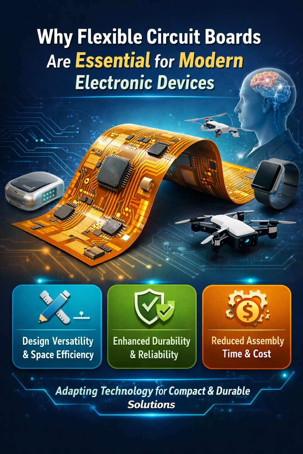
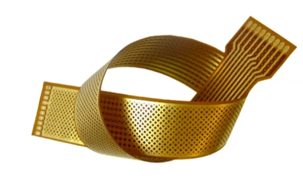
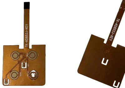
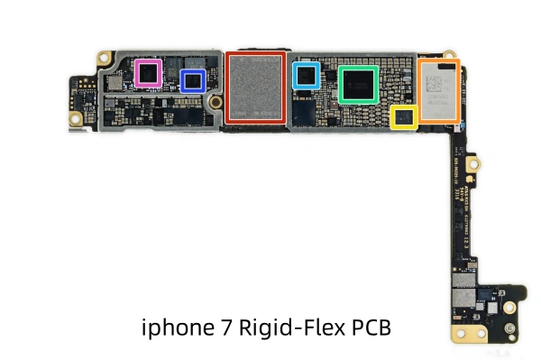
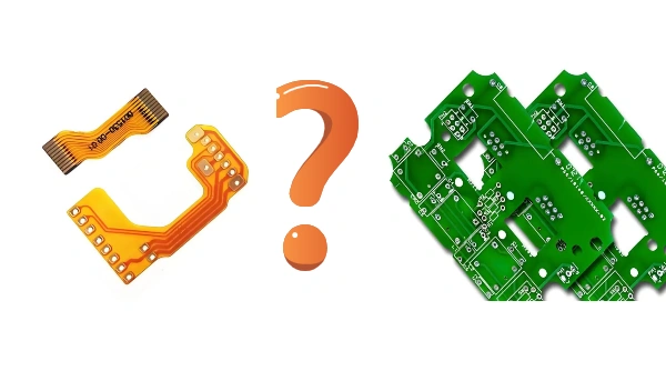
The advent of Flexible Printed Circuits (FPC) and traditional Printed Circuit Boards (PCB) has given rise to the rigid-flex PCB. In PCB prototyping, flexible circuits and rigid circuits are combined through lamination and other processes according to specific technological requirements, resulting in a unique rigid-flex PCB. This board integrates the flexibility of FPC with the robustness of traditional PCB, often referred to as a rigid-flex PCB or flex-rigid PCB. It is used in products with special requirements, featuring both flexible and rigid areas. This helps save internal space, reduce the overall product volume, and enhance performance. However, producing rigid-flex PCBs is challenging, with a low yield rate, making them more expensive and time-consuming to manufacture.
Advantages of Rigid-Flex PCB
- Maximized Space Utilization: Rigid-flex PCBs use a 3D routing design, allowing more efficient use of internal space compared to traditional rigid PCBs. This design is ideal for devices with strict space constraints, such as smartphones and wearable devices, enabling designers to integrate more functionality into a smaller volume.
- Reduced Device Weight: Due to the lightweight nature of flexible circuits, rigid-flex PCBs can significantly reduce the overall weight of the product. This is particularly important in aerospace and portable electronic devices, helping meet weight restrictions.
- Enhanced System Reliability: Rigid-flex PCBs reduce the need for connectors and plugs, thereby decreasing potential failure points. The flexible sections effectively distribute mechanical stress, reduce the burden on solder joints, and mitigate the risk of damage from vibrations and impacts, thus improving circuit reliability.
- Improved Electrical Performance: In high-frequency applications, rigid-flex PCBs can effectively control impedance and reduce signal loss. The flexible sections can be designed as precise transmission lines to maintain signal integrity, making them suitable for high-frequency communication devices and high-speed data transmission applications.
- Simplified Production Process: By reducing the number of components and connections, rigid-flex PCBs simplify the assembly and testing processes. This not only shortens the production cycle but also lowers manufacturing costs and increases production efficiency.
- Enhanced Thermal Management: In high-power density applications, rigid-flex PCBs manage heat more effectively. The design of the flexible sections aids in heat dissipation, improving overall thermal performance and stability of the system.
- Increased Durability: The flexible part of the PCB can withstand repeated bending, making rigid-flex PCBs especially suitable for applications requiring frequent movement or bending, such as in wearable devices and notebook hinge sections.
Disadvantages of Rigid-Flex PCB
- Higher Costs: The manufacturing process for rigid-flex PCBs is more complex than for traditional rigid PCBs. This complexity arises from combining flexible and rigid materials, special lamination processes, and precise processing requirements. Consequently, the cost of rigid-flex PCBs is generally higher than that of standard rigid PCBs, especially for small batch production.
- Complex Design: Designing a rigid-flex PCB involves multiple considerations, including the connection between flexible and rigid parts, the electrical and mechanical performance of bend areas, and the overall layout optimization. These complex design requirements may lead to longer design cycles and increased difficulty. Additionally, different materials’ physical and electrical properties must be considered to ensure compatibility in actual applications.
- Testing Difficulties: Due to the complex structure of rigid-flex PCBs, including the combination of flexible and rigid areas and different materials, the testing process can become more challenging. Testing equipment needs to adapt to these complex structures, and testing methods must be tailored to the specific characteristics of rigid-flex PCBs. For instance, ensuring electrical performance and reliability in a bent state may require additional testing steps and equipment.
- Longer Production Cycle: The production process for rigid-flex PCBs usually involves multiple steps, such as lamination, laser cutting, and precision machining. Due to the complexity of these steps, the production cycle may be longer than that of traditional rigid PCBs. This not only affects delivery times but may also impact production schedule flexibility, especially in cases requiring rapid response to market demand changes.
Differences Between Rigid-Flex PCBs and Rigid PCBs
Rigid-Flex PCBs and Rigid PCBs have significant differences. Rigid-Flex PCBs combine flexible and rigid materials, allowing bending and folding on the same board, making them suitable for complex 3D designs and space-constrained applications like smartphones and wearable devices. This design enhances space utilization, reduces device weight, and can withstand dynamic stress. However, the manufacturing cost is higher, and the design and testing processes are more complex.
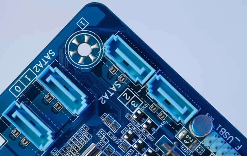
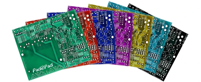
In contrast, Rigid PCBs are made entirely of rigid materials and are designed to be rigid, suitable for 2D planar routing. Their manufacturing process is mature and cost-effective, suitable for applications with stable structures such as computer motherboards and household appliances. While Rigid PCBs are less flexible in weight and space optimization, they offer clear advantages in cost and manufacturing processes.
In summary, Rigid-Flex PCBs excel in design flexibility and weight optimization, while Rigid PCBs are more advantageous in cost efficiency and manufacturing processes.
Rigid-Flex PCB Design
Material Selection
- Material Compatibility: Ensure that the chosen flexible and rigid materials bond effectively during lamination to avoid delamination and poor adhesion.
- Thermal Performance: Consider the thermal expansion coefficients of materials to prevent mechanical stress and electrical issues caused by thermal expansion and contraction.
Routing Design
- Signal Integrity: Design routing paths to be as short as possible and avoid sharp angles to minimize signal interference and delay.
- Flexible Area Design: Avoid sharp bends and angles in the flexible sections to reduce mechanical damage and signal distortion due to bending.
- Via Design: Choose appropriate via types and positions, avoiding placing vias in bending areas of the flexible section to prevent stress concentration and electrical failure.
Mechanical Design
- Bending and Flex Radius: Ensure that the bend radius of the flexible sections meets manufacturer requirements to avoid material rupture from excessive bending.
- Connection Strength: Design the connection between flexible and rigid parts to ensure that connection areas do not detach or get damaged during bending and dynamic use.
Manufacturing and Testing
- Lamination Process: Use appropriate lamination temperatures and pressures to ensure strong bonding between flexible and rigid materials.
- Testing Plans: Include durability testing (e.g., bending durability, thermal cycling) and electrical testing (e.g., impedance testing) to ensure circuit reliability in actual use.
- Production Specifications: Follow manufacturer design and production specifications to ensure that designs meet manufacturing standards and avoid defects due to process issues.
Rigid-Flex PCB Technology
- Lamination Technology
- Multi-layer Lamination: Combine flexible and rigid materials through multi-layer lamination processes, usually involving high-temperature and high-pressure lamination to ensure strong material bonding.
- Adhesives: Use specialized adhesives (e.g., epoxy resins) to bond flexible and rigid materials together. The choice of adhesive should consider its electrical and mechanical properties to ensure reliable inter-layer adhesion.
- Flexible Circuit Materials
- Polyimide (PI): Commonly used in flexible circuits, offering excellent high-temperature resistance, chemical stability, and flexibility.
- Polyester (PET): Sometimes used for low-cost applications, providing good flexibility and electrical performance, but with poorer high-temperature resistance.
- Rigid Material Processing
- FR-4: The most common rigid material, providing good insulation and mechanical strength. Ensure proper bonding with the flexible section during lamination.
- Copper Foil Layers: Used for conductive layers; ensure good adhesion to insulating materials during lamination to avoid delamination and signal loss.
- Routing and Design Techniques
- Design Tools: Use advanced PCB design software (e.g., Altium Designer, Cadence) for routing and layout design, supporting complex 3D layouts and multi-layer designs.
- Signal Integrity Analysis: Conduct signal integrity analysis to ensure routing paths and via designs do not cause signal interference or delay.
- Bending Design: Consider the bending radius of flexible sections to avoid over-bending and reduce mechanical stress on the circuit.
- Mechanical Processing
- Laser Cutting: Used for precise cutting of flexible and rigid materials, especially for complex shapes and detailed processing.
- Drilling and Milling: Drill and mill rigid sections to ensure component installation and connections, while avoiding impact on flexible areas.
- Testing and Quality Control
- Durability Testing: Includes folding tests, thermal cycling tests, and mechanical stress tests to verify the reliability of flexible sections in actual use.
- Electrical Testing: Perform impedance testing, contact testing, and short-circuit/open-circuit testing to ensure electrical performance meets design specifications.
- Visual Inspection: Use high-resolution cameras for visual inspection to ensure no defects or errors during manufacturing.
- Assembly Technology
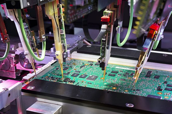
- Surface Mount Technology (SMT): Install surface-mount components on rigid-flex PCBs, ensuring proper placement between flexible and rigid areas.
- Soldering and Connections: Use precision soldering techniques to ensure stability of solder joints in flexible areas and avoid damage to flexible materials during soldering.
- Design Standards and Specifications
- IPC Standards: Follow relevant standards from the International Printed Circuit Association (IPC), such as IPC-2223 (Flexible Circuit Board Design Standards) and IPC-A-610 (Electronic Assemblies Acceptance Standard), to ensure quality in design and manufacturing processes.
Applications of Rigid-Flex PCBs
- Consumer Electronics: Rigid-flex PCBs are used in devices such as smartphones and tablets to achieve compact designs and high integration levels.
- Wearable Devices: Smartwatches and health monitoring devices leverage the flexibility and lightweight nature of rigid-flex PCBs to integrate various functions.
- Medical Equipment: Used in medical imaging devices and implantable medical instruments, rigid-flex PCBs provide reliable functionality and durability.
- Aerospace: Rigid-flex PCBs are employed in spacecraft and aircraft instruments to meet spatial and performance requirements.
- Automotive Electronics: Used in Advanced Driver Assistance Systems (ADAS) and in-car entertainment systems for compact and integrated designs.
- Industrial Equipment: Provides high-density wiring and flexible electrical connections in automation control systems and robotics.
- Communication Equipment: Used in base stations, routers, and wireless devices to support high-speed data transmission and compact designs.
- Military and Defense: Applied in military electronics and defense systems to meet high durability and reliability requirements.

How to Find a Reliable Rigid-Flex PCB Manufacturer
Greatpcb is a professional PCB and PCB assembly manufacturer with over 15 years of experience. We offer one-stop services ranging from PCB (1-20 layers) to PCBA, equipped with advanced automation production equipment to support quick-turn prototyping. We can meet any custom PCB requirements you may have.
Greatpcb’s Rigid-Flex PCB Manufacturing Capabilities:
- Experience: Over 15 years in the industry, specializing in both rigid and flexible PCBs.
- Advanced Equipment: State-of-the-art automated production facilities for efficient and high-quality manufacturing.
- Customization: Ability to meet diverse and complex PCB design and manufacturing requirements.
- Rapid Turnaround: Quick production capabilities for fast turnaround on prototypes and small batches.
For reliable rigid-flex PCB manufacturing, consider Greatpcb for your next project, ensuring quality, efficiency, and expertise.


