Experience in Designing AC/DC Power Supply PCBs

Introduction
An AC/DC power supply, also known as an AC/DC converter, is a vital component in many electronic applications, including consumer electronics, industrial systems, robotics, medical, and military applications.
Current Trends
Current trends indicate a move towards lower power supply voltages (especially for highly integrated digital devices), smaller footprints, lighter weights, and higher efficiencies. This necessitates precise power circuit design starting from the PCB level.
Complexity of Power Rails
Modern electronic applications often require five or more independent power rails with different electrical characteristics and performances. Such requirements complicate power supply design, as it is the first component of an electronic device, and its proper operation, reliability, and lifespan depend on it.
Overview of Design Challenges
This article will discuss the main challenges engineers face when designing AC/DC power supply PCBs, such as signal integrity, power rail integrity, electromagnetic interference (EMI), output voltage stability, and thermal management. By following some straightforward guidelines presented here, designers can anticipate these issues and prevent them from negatively impacting PCB design.
Types of AC/DC Power Supplies
When selecting the most suitable AC/DC power supply for project requirements, several key factors must be considered, including:
- Type (Custom or Integrated): Design based on discrete components or integrated regulators/converters (ICs).
- Technology: Linear or switching.
- Electrical Characteristics: Input voltage range, output voltage type (fixed or variable, single output or multiple outputs), output power, efficiency, etc.
- Mechanical Characteristics: Open or closed design, size, weight, cooling systems, etc.

Integrated Devices vs. Discrete Components
For the first point, it’s often best to use integrated devices, which offer multiple advantages, including simplified projects, reduced BOM and time-to-market, and integrated protection and diagnostic features. However, for some high-power, RF, or niche applications, designs based solely on discrete power components may be required.
Choosing Between Linear and Switching Power Supplies
Regarding the technology used, the choice between linear and switching power supplies (also known as SMPS, or Switched Mode Power Supply) depends on the specific application requirements.
Linear Power Supplies
Linear power supplies can be considered the oldest yet still relevant conversion technology. Despite their limitations in efficiency and associated power loss as heat, they are successfully used in applications requiring high reliability, low noise, fast recovery and response times, and negligible radiation emissions.
A significant category of linear power supplies is the Low-Dropout (LDO) regulator. To maximize LDO efficiency, it’s essential to minimize the difference between input voltage and regulated output voltage. Additionally, selecting regulators with low thermal resistance helps prevent overheating beyond optimal operating temperatures.
Advantages of Switching Power Supplies
Switching power supplies have become the standard for converting AC voltage to DC voltage. This conversion is nonlinear and usually operates in a closed-loop manner, using feedback signals to maintain regulation. While switching regulators are preferred for their efficiency and regulation quality, their design can be complex due to the involvement of multiple components, some of which include large passive components (inductors and capacitors) that may introduce noise if not placed correctly.
Comparing Linear and Switching Technologies
Although SMPS requires more complex design, they ensure very high efficiency, exceeding that of the best linear supplies, allowing for better thermal management. However, the high-frequency switching components generate significant electromagnetic noise, which can affect the quality of signal transmission and potentially lead to component failure or damage. Consequently, linear technology is often preferred for electronic medical applications and laboratory instruments.
Importance of PCB Layout and Routing
In AC/DC power supply PCBs, layout plays a critical role as it directly affects immunity to electromagnetic interference, signal and power integrity, power efficiency, thermal management, and reliability of the same device.
Enhancing Power Conversion Efficiency
Good layout practices can enhance power conversion efficiency, dissipate heat from the hottest components, and reduce noise levels. In this regard, the proper sizing of conductive traces is a key factor in minimizing generated heat and ensuring PCB reliability under various load conditions. Poor layout can lead to problems when handling large currents or significant voltage differentials between input and output.
Effective Routing Rules
Some simple yet effective routing rules include:
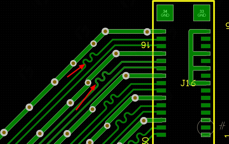
- Use the shortest and straightest traces possible to connect power devices.
- Avoid inserting curves or sharp edges into traces, as these can concentrate electric fields at specific points on the PCB.
- Keep traces with significant voltage differentials adequately spaced apart.
- Avoid placing high-voltage traces in the innermost layers of the PCB; instead, increase the distance between traces in the innermost layer.
- Route traces carrying sensitive or high data rate signals away from power traces and regulators, especially switching types.
- In multilayer PCBs, sensitive signal traces should be placed on layers separated from power line layers by a solid (possibly ground) layer.
- To prevent signal coupling (which can cause noise or interference), signal traces should not be laid parallel to power traces and should ideally cross at 90° angles to minimize noise coupling.
- Place high current traces on the outer layers. If this is not feasible, use vias to connect multiple layers together. For higher currents, multiple vias may be necessary. Note that a 14 mil diameter via allows for currents up to 2A, while a 40 mil diameter or larger via allows up to 5A.
- For ground planes, use solid, uninterrupted areas or large polygons. These areas provide low impedance paths that can dissipate noise and handle high return currents. They also offer a pathway to dissipate heat from critical components. Ground planes on both sides help absorb radiated EMI, reducing ground loop noise and errors.

#image_title
Managing Electromagnetic Interference
The design of AC/DC converters must comply with strict safety and electromagnetic interference regulations. In this regard, it may be necessary to insert appropriate EMI filters to meet standard requirements.
Testing and Mitigation Strategies
Some possible measures include:
- Conduct initial testing (without adding any filters) to assess the impact of EMI generation.
- Identify the frequencies that cause the most issues.
- Take action on trace routing to keep power lines and sensitive signals as far apart as possible.
- Eliminate ground loops.
- As a last resort, design external filters by adding inductive components in series at the AC input of the AC/DC power supply.
Importance of PCB Stackup
The PCB stackup, determined by the configuration and arrangement of the internal layers, is a critical factor affecting the circuit board’s EMC performance. In fact, a well-designed stackup can reduce the radiation emitted from closed paths (differential mode radiation) and the radiation generated by connected cables (common mode radiation).
Shielding and Noise Immunity
To provide adequate electromagnetic shielding and improve immunity to noise and crosstalk, it is advisable to introduce at least one solid ground layer in the PCB stackup if space permits. If it is not possible to maintain an entire layer due to space constraints, consider limiting a covering area to the minimum necessary that encompasses the power components of the PCB.
Component Placement Strategies
The first components to place on the PCB are those that carry high currents, as they require the widest traces. Components that make up the power PCB should be placed as close together as possible and positioned to minimize trace lengths while keeping in mind that related traces must be as short as possible.
Managing Thermal Considerations
Thermal considerations must also be accounted for when placing components, prioritizing optimal locations for dissipating heat from power devices. It’s recommended to start with important components such as the converter IC, followed by input capacitors and inductors, and then the output capacitors.
Reducing Parasitic Inductance
Loops with high switching currents (i.e., loops with high di/dt values) must be as narrow and compact as possible to reduce parasitic inductance that can cause voltage spikes. A good rule of thumb is to overlap or place the current distribution and return paths adjacent to each other to minimize the loop area formed and reduce electromagnetic interference.
Organizing Analog Control Components
Analog control components should be placed last as they take up less space and require thinner traces. One approach is to create subgroups based on functionality and link them by group.
Placement of Large Components
All large components, such as MOSFETs, rectifiers, electrolytic capacitors, inductors, and connectors, should be placed on the top side of the PCB to avoid falling or shifting during soldering. The bottom side should only contain the minimal components that adhere to the PCB through surface tension and will not move during machine soldering operations.
Role of Bypass Capacitors
Bypass capacitors, also known as decoupling capacitors, are used to protect the most sensitive components, such as ICs and logic devices, where minor oscillations could be misinterpreted as changes in logic states. These capacitors must be grounded and placed as close to the IC’s power pins as possible.
Thermal Management Strategies
Since all power circuits generate heat, the design of power PCBs typically requires adequate thermal management features. The first rule to follow is to make connections as short and straight as possible while separating heat-generating components (IC regulators, MOSFETs, etc.) from thermally sensitive components.
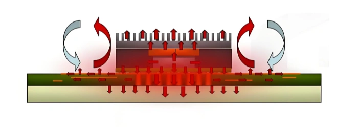
Utilizing Copper Areas for Heat Dissipation
Then, considering the high thermal conductivity of copper, it may be beneficial to use copper areas more extensively to provide heat dissipation zones. These copper-covered areas will help distribute heat more evenly, transferring it from hotspots to areas with better thermal conductivity, ultimately achieving better heat dissipation.
Thermal Vias and Cooling Solutions
Using thermal vias and solid copper areas below the hottest components is another effective method to quickly dissipate heat from these components. The goal is to prevent hotspots on the PCB and allow heat to dissipate rapidly without damaging the most critical components.
Conclusion: Ensuring Reliable Performance
If layout is insufficient to ensure good thermal management, heatsinks can be used on power components, and ultimately active cooling solutions, such as forced ventilation, can be introduced. These options depend entirely on the application, and it’s important to remember that in some cases, fanless power supplies are typically preferred for reliability and noise control reasons.
#image_title
By understanding and addressing the design challenges associated with AC/DC power supplies, engineers can create more efficient, reliable, and compact power solutions for a wide range of applications. Through careful consideration of component selection, layout strategies, thermal management, and EMI mitigation, designers can significantly enhance the performance and longevity of their power supply systems.
Table of Contents

Tags
Related Posts
PCBA Prototype
July 21, 2026
PCBA Prototype
July 17, 2026