FOC (Field Oriented Control) Explained for Beginners

Brushless Motor FOC Control
With FOC (Field Oriented Control) algorithms, you can control the rotation of a brushless motor in various ways. This has widespread applications in robotics as well.
FOC System
The FOC system is a closed-loop system where the controller receives current and angle signals from sensors and then computes the required motor speed, position, and torque based on the commands we provide. It then converts these calculations into corresponding electrical signals to control the motor’s rotation. The core of this system is the calculation method, which is the FOC algorithm. To understand what the FOC algorithm is calculating, we need to first look at the control principles of a brushless motor.

Internal Structure of a Brushless Motor
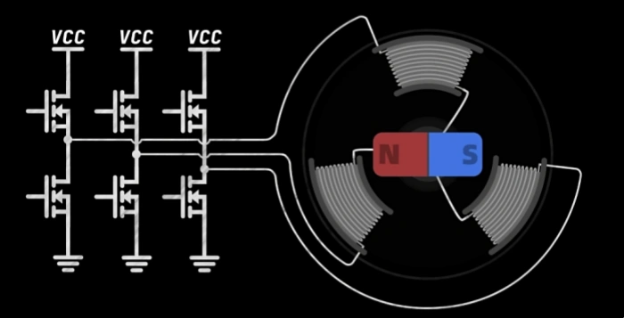
As shown in the diagram below, there are three coils arranged around the motor, which are connected to six MOSFETs outside. When in operation, the coils remain stationary and are referred to as the stator. In the middle, there is a rotating magnet, known as the rotor.
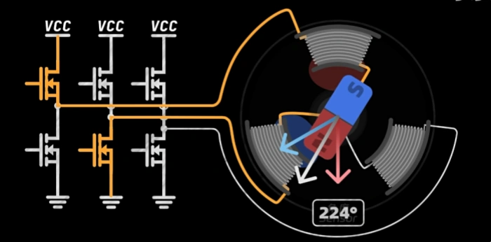
When two MOSFETs are turned on, current flows into the two coils, generating a magnetic field. When the two magnetic fields overlap, they create a magnetic field that causes the rotor to rotate. When the rotor overlaps with the magnetic field, the controller switches to another MOSFET to continue rotating the rotor.

We can also turn on all three MOSFETs, causing current to flow into all three coils, generating three magnetic fields that combine to create a stronger magnetic field than with just two. Below is a diagram of different switching combinations that can produce six different magnetic fields. By continuously switching between these fields, the rotor can be driven to rotate.

This is the basic principle of brushless motor control.
Creating a Precise, Controllable Magnetic Field
Basic brushless motor control essentially just makes the motor rotate, replacing the traditional brushed motors. For example, the brushless motor controllers used in remote-controlled aircraft or electric hairdryers use this principle. However, some products require more than just making the motor rotate; they need more precise control, such as in electric toothbrushes, which demand precise motor control. This precise control includes allowing the motor to rotate at any speed, stay at any position, and adjust its torque. These are the problems that the FOC algorithm addresses.
How Does the FOC Algorithm Achieve Precise Control?
Controlling Magnetic Fields in Any Direction
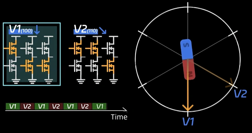
We need to generate magnetic fields in any direction. As mentioned earlier, there are six different magnetic fields generated by switching MOSFETs. Now, we switch between V1 and V2 for 0.5ms back and forth. By repeating this process, the rotor will oscillate back and forth between the magnetic fields of V1 and V2. However, if the switching speed of the magnetic field is fast enough, beyond the response time of the rotor, the rotor will remain in the center and not move, effectively creating a new magnetic field.
At this point, by adjusting the time ratio of the initial magnetic fields in a time cycle, we can synthesize any magnetic field within this range. The same method can be applied to switch between adjacent magnetic fields, allowing us to create magnetic fields in any direction within a 360° range.

Controlling Magnetic Field Strength
At this point, we have only created magnetic fields in any direction. We also need to control the strength of the magnetic field. The method is simple: when the three MOSFETs in the same alignment are turned on, the coils have no voltage but do have current, because the coils are inductive, and inductance has a continuity effect that prevents the current from changing abruptly. Therefore, the current can only decay at a certain rate rather than dropping to zero instantly. This is why the zero vector always requires three upper MOSFETs or three lower MOSFETs to be turned on, rather than having all six MOSFETs closed. By inserting a zero magnetic field state within a time cycle and adjusting the time proportion, we can control the strength of the magnetic field at will. Thus, we have now created a magnetic field whose direction and strength can be controlled.

Rotor and Magnetic Field Alignment
At this point, you may think that we simply need to generate a magnetic field in the direction we want the rotor to rotate, but it’s not quite that simple. First, we need to use an angle sensor to detect the current position of the rotor and then generate a magnetic field that is always perpendicular to that direction. This magnetic field will attract the rotor to move toward it. As soon as the rotor moves even slightly, the magnetic field will follow it to maintain perpendicular alignment. This is because the force generated in this configuration is the strongest and the efficiency is the highest.

Once we have this idea, the only parameter we need to adjust is the magnetic field strength. By controlling the magnetic field strength, we can control the position, speed, and torque of the brushless motor. For example, if we want the motor to rotate faster, we increase the magnetic field strength. If we want the motor to stop, we apply a negative magnetic field, generating a counterforce. When the rotor stops, we can set the magnetic field strength to zero. If there is an external disturbance that shifts the rotor’s position, we can apply the magnetic field to bring the rotor back. This is the basis of FOC.
Closed-Loop System
A complete FOC algorithm is a closed-loop system. The magnetic field strength mentioned earlier is calculated using data from sensors and the commands we issue, through PID calculations. In practice, we use current to replace the magnetic field because the current in the coils is closely related to the magnetic field: their directions are aligned, and their magnitudes are proportional. Additionally, using current sensors makes it more convenient. Therefore, the actual FOC topology structure includes current loops, speed loops, and position loops for feedback. The system will decide how to control the MOSFET switches based on the input control commands and sensor data.

Related Posts
PCBA Prototype
December 14, 2025
PCB Assembly
September 2, 2025


