Understanding Insertion Loss in High-Speed PCB Design

Can Signal Attenuation Occur Even in PCB Traces with Near-Zero Resistance?
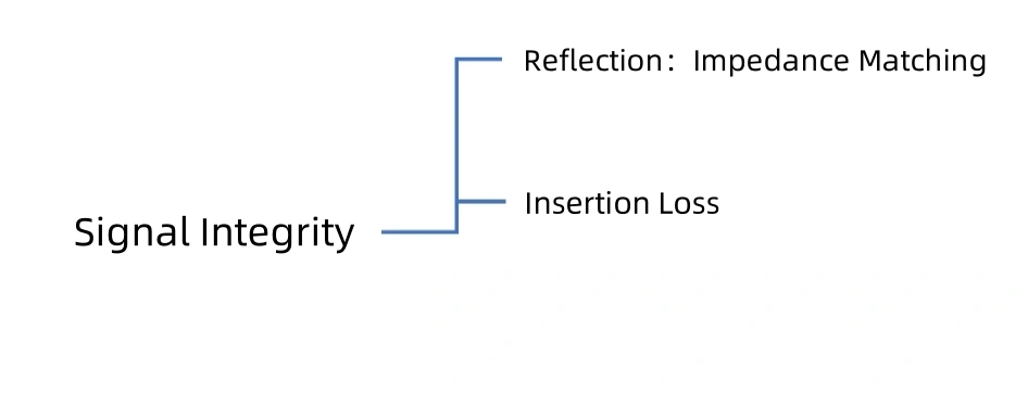
When designing high-speed PCBs, signal integrity is a key concern. Signal integrity refers to the ability of a signal to be transmitted from the source to the destination without distortion.
There are several reasons why signals may become distorted, one of which is reflection caused by uneven transmission media. In a previous article, High-Speed PCB Design: Impedance Matching Essentials, we discussed how impedance matching can reduce reflections. However, even without reflections, signals may still become distorted as they pass through PCB traces. In this article, we will explore another crucial aspect of signal integrity: insertion loss.
What is Insertion Loss?
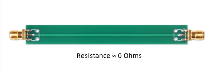
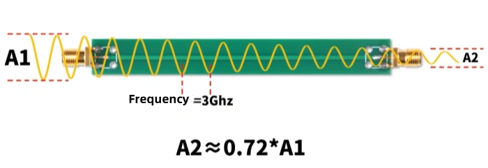
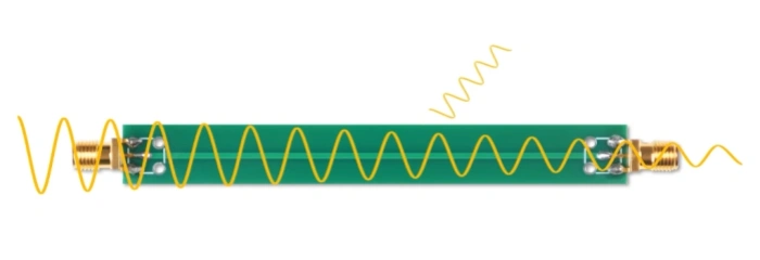
To understand insertion loss, we can conduct a simple experiment. As shown in the diagram, this is a typical PCB with a standard trace. For testing purposes, I soldered SMA connectors to both ends and measured the trace’s resistance using a multimeter, which read 0 ohms.
Next, we need a network analyzer. By connecting the two ports of the network analyzer to the PCB’s SMA connectors, we create a loop. The analyzer sends a sine wave from one end and receives it at the other.
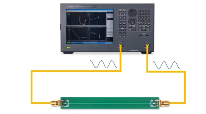
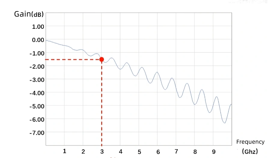
Logically, the output sine wave and the received sine wave should have identical amplitudes. However, in reality, this is not the case. The network analyzer measures the amplitude (power) at both ports and generates a report. When examining the report, at a frequency of 3GHz, we see a gain reduction of 1.4dB. This means that after passing through the PCB, the sine wave’s amplitude is only about 72% of the original, with the remaining 28% lost in the PCB trace. This loss is known as insertion loss.
![]()
Why Does Low-Resistance Tracing Still Cause Loss?
Even though the trace resistance is nearly zero, the signal still attenuates. Insertion loss primarily comprises three components:
- Dielectric Loss: Under an electric field, insulating materials experience energy loss due to dielectric conduction and polarization lag. Simply put, part of the signal’s energy is absorbed by the PCB’s substrate, similar to how food absorbs electromagnetic waves in a microwave.
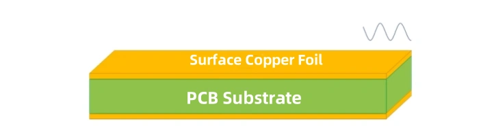
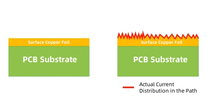
- Conductor Loss: Skin effect occurs when alternating current flows through a conductor, causing current to concentrate in a thin layer near the conductor’s surface. High-frequency current typically flows along the conductor’s surface, reducing the effective cross-sectional area and increasing resistance. Additionally, the surface of copper foil is not perfectly smooth; microscopic irregularities increase the current path length, further adding to the series resistance and resulting in additional loss.
- Radiation Loss: Any wire can act as an antenna, radiating part of the energy and leading to signal attenuation.
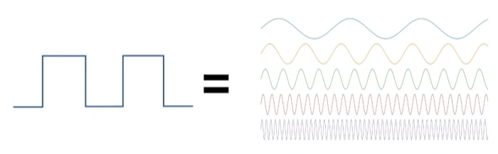
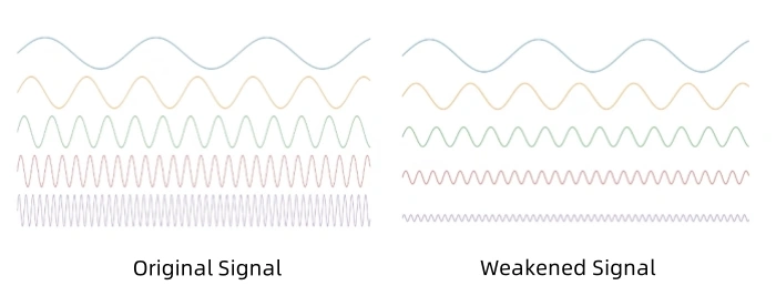
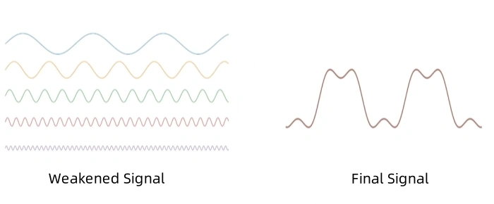
These three types of losses contribute to signal attenuation or distortion in PCB traces. The test report also shows that insertion loss is positively correlated with sine wave frequency—the higher the frequency, the greater the loss. Insertion loss compromises signal integrity, as any square wave signal can be decomposed into multiple sine waves of varying frequencies. While low-frequency components pass through the trace effectively, high-frequency components attenuate significantly, resulting in a distorted square wave at the output.
Typically, the frequencies of square waves used in applications such as UART or SPI are relatively low (often only tens of MHz). Even if the high-frequency components are attenuated, the signal distortion is minimal. However, at higher frequencies, such as those used in DDR signals in the tens of GHz, insertion loss becomes a critical concern.
How to Reduce Insertion Loss
How can we reduce insertion loss? To address this, we conducted an experimental test comparing the effects of different materials and trace lengths. In the experiment, we used 9cm FR-4 material, 9cm Teflon material, and 27cm FR-4 material for comparison.
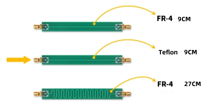
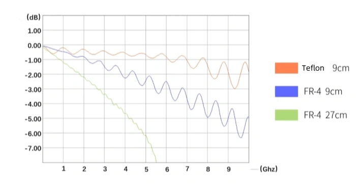
Based on the experimental results, it is evident that the insertion loss of Teflon material PCB is lower than that of FR-4 material, while the third PCB has the highest insertion loss. Thus, we can draw the following two conclusions:
- The shorter the trace length of the PCB, the smaller the insertion loss.
- Changing the PCB substrate material can also reduce insertion loss.
However, what we are mainly reducing here is the dielectric loss, which indirectly decreases the insertion loss. This leads us to the question: how can I determine which substrate material to use to reduce insertion loss? The answer is simple; we should focus on the dielectric constant and the loss tangent of the material. Generally, the lower the dielectric constant and the loss tangent, the smaller the insertion loss. For example, the dielectric constant of FR-4 is 4.2-4.8, and the loss tangent is 0.014-0.02, while the dielectric constant of Teflon is 2.55-2.94, and the loss tangent is 0.0016-0.0019. The difference is significant.
Balancing Material Selection and Cost
While low-insertion-loss materials can significantly improve signal integrity, cost considerations are also important. High-quality materials like Teflon often cost 5 to 10 times more than FR-4. In most cases, cost control remains a priority, and even PCBs with numerous high-speed signals, such as those in motherboards and graphics cards, typically use FR-4 as the standard material.
To mitigate the signal attenuation caused by FR-4, chip manufacturers often incorporate pre-emphasis circuitry. Although high-frequency components tend to attenuate, boosting them at the transmission end ensures that the received signal remains intact even after attenuation. As a result, FR-4 remains the recommended material for high-speed digital circuits, provided that trace lengths are kept within reasonable limits to avoid excessive attenuation.
Conclusion
In high-speed PCB design, insertion loss is a significant factor affecting signal integrity. Although low-insertion-loss materials can enhance signal transmission quality, cost-effectiveness must also be considered. By carefully selecting PCB substrates and optimizing trace design, it is possible to strike a balance between performance and cost, ensuring both signal integrity and system reliability.
Table of Contents

Tags
Related Posts
PCBA Prototype
July 21, 2026
PCBA Prototype
July 17, 2026