Series Resistors in PCB Design for USB Connections

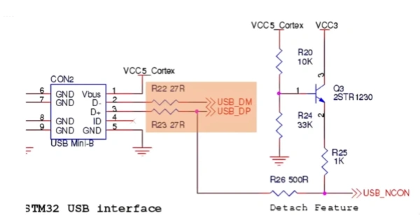
In circuit design, it’s common to see resistors in series with the data lines (D+ and D−) of USB interfaces on schematics. These resistors are often explained as being for impedance matching. However, after reviewing multiple schematics, you’ll notice that the values of these resistors vary—sometimes they’re 22Ω, sometimes 33Ω, and in some cases, there are no resistors at all. So, are these series resistors necessary? If so, what value should be used? And what’s the purpose of a 0Ω resistor? These are the questions we’ll explore today.
USB Standards and Impedance Matching
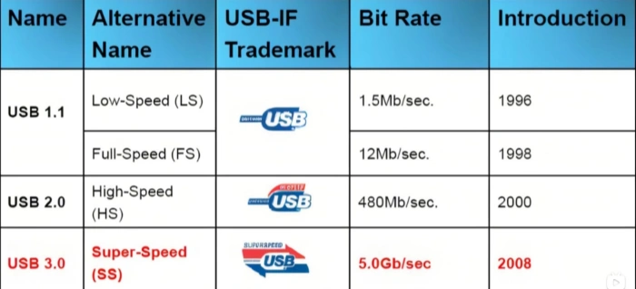
First, let’s refer to the USB standards to understand the impedance matching requirements. The USB 2.0 standard specifies three data transfer speeds: Low-Speed (1.5 Mbps, compatible with USB 1.0), Full-Speed (12 Mbps, compatible with USB 1.1), and High-Speed (480 Mbps). Chapter 7 of the standard outlines key points related to transmission line and driver impedance matching:
- Full-Speed USB connections: These use shielded twisted-pair cables with a differential characteristic impedance of 90Ω ±15%.
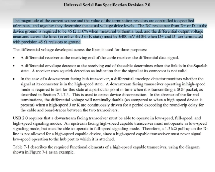
- High-Speed transceivers operating in Full-Speed or Low-Speed modes: Must have a driver impedance of 45Ω ±10%.
- Transceivers that do not support High-Speed mode: The driver’s output impedance must be between 28Ω and 44Ω.
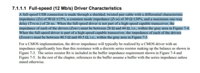
For circuit design and PCB layout, two critical points are:
- 90Ω differential impedance for PCB traces: The width and spacing of the traces must be calculated based on the characteristics of the board material, and layout software typically includes tools to help with this calculation.
- Driver impedance matching: The driver’s internal impedance plus the series resistor must equal 45Ω, with a tolerance of less than 5Ω, to match the 45Ω single-ended impedance of the transmission line.
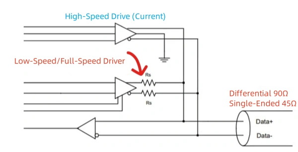
Driver Impedance and Series Resistors
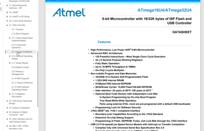
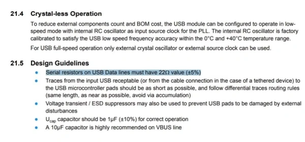
To determine the driver’s internal impedance, you should consult the chip’s datasheet. For instance, the design guide for the ATMEL Mega 32 chip recommends a 22Ω resistor with 5% tolerance in series with the USB data lines. This is why you often see 22Ω resistors on the schematics of Arduino development boards.
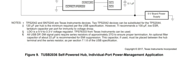
Similarly, TI’s USB Hub chip requires approximately 27Ω resistors in series with all USB DP/DM signal lines to ensure proper termination matching. The AD USB isolation chip’s datasheet specifies that in Full-Speed mode, each D+ and D− data line on the device side should have a 24Ω ±1% resistor in series, while in Low-Speed mode, no series resistors are required.

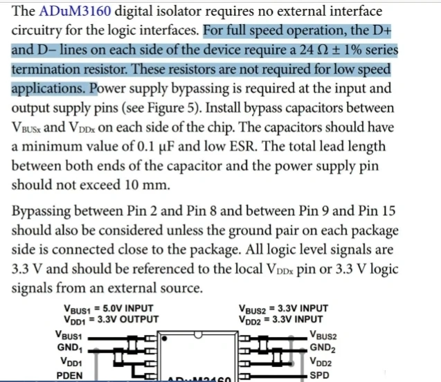
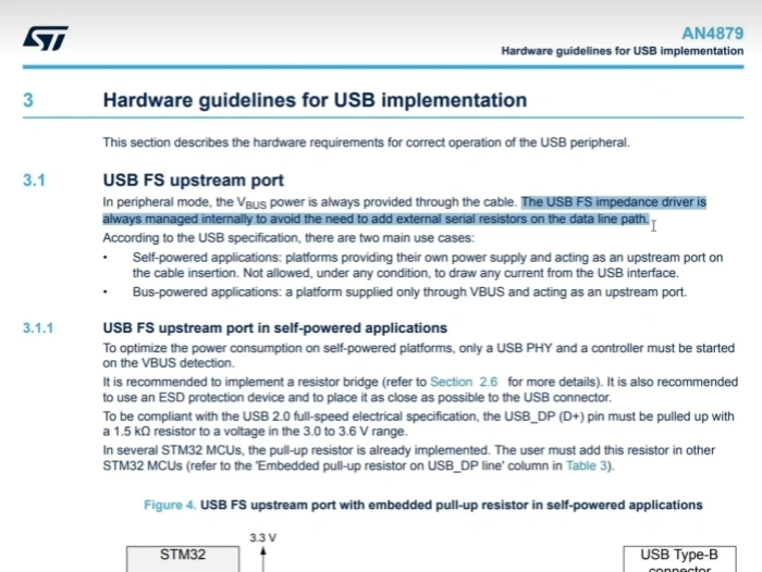
These examples highlight that the required series resistor value can vary depending on the chip, underscoring the importance of consulting the datasheet. In some cases, manufacturers have integrated these resistors into the chip itself. For example, the STM32 chip’s datasheet notes that USB data lines do not require series resistors because they are already built into the chip.
0Ω Resistors and Post-Production Tuning
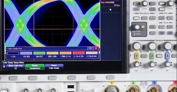
If the 90Ω differential impedance of PCB traces cannot be fully achieved, a 0Ω resistor might be used to facilitate post-production tuning. The final resistor value can be determined based on signal integrity metrics, such as eye diagrams.
Conclusion
In conclusion, the series resistor value for USB data lines should be chosen based on the driver’s internal impedance and design requirements. Whether a series resistor is needed and what value should be used should be determined by the chip’s datasheet. This conclusion can also be extended to impedance matching for other data buses, such as Ethernet, HDMI, PCIe, and 1394.
Related Posts
PCBA Prototype
November 9, 2025


