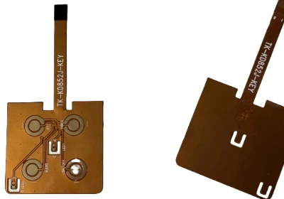
The Structure and Design of FPC
About FPC (Flexible Printed Circuit)
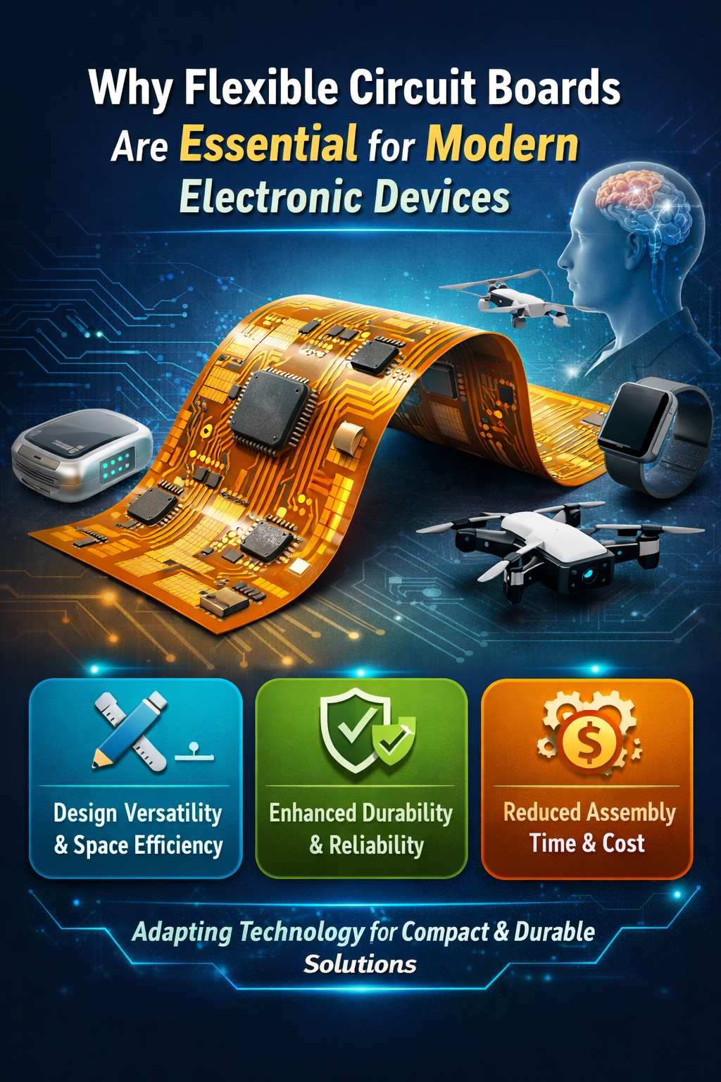
FPC, or Flexible Printed Circuit, refers to a type of circuit board that can be bent and flexed, and is widely used in portable electronic devices today. Depending on the installation and application, FPCs can be categorized into three types:
- One-Time Fold (One Time) This type of FPC is designed to be folded only once during its entire lifespan. After this single fold, the FPC is not expected to undergo further bending or changes.
- Static Flexible Circuit Board (Flex to Install || Static Flex) This FPC is bent only during the assembly of the product and then remains in a relatively fixed position.
- Dynamic Flexible Circuit Board (Dynamic) This type of FPC is designed to endure thousands of bends and movements during the operation of the product.
Structure of FPC
The structure of an FPC is similar to that of a rigid PCB, but the materials used differ. FPCs are categorized based on the number of copper layers into single-layer, double-layer, and multi-layer boards.
Single-Layer FPC Structure
In a single-layer FPC, the substrate and cover layers are made from the same material, with a copper foil layer on each side of the substrate. The copper foil and cover layers are bonded together with adhesive.

Double-Layer FPC Structure
In a double-layer FPC, there is a copper foil layer on each side of the substrate. These copper foil layers are fixed to the substrate with adhesive or through lamination without adhesive. The outer layers are then covered with an additional adhesive and cover layer, creating the final double-layer FPC structure.

Multi-Layer FPC Structure
A multi-layer FPC is composed of multiple single-layer or double-layer FPCs stacked together.

FPC Stacking Structure

In FPC stacking, the thickness of adhesive-free layers is thinner, making them more flexible in practice. The design of FPC stacking should include not only the stacking sequence but also the thickness and material information of each layer. For the most accurate and direct information, it is best to contact Greatpcb, which will provide the necessary data references.
Enhancing Flexibility of FPC
The primary characteristic of FPC is its flexibility. To improve flexibility, especially for products with high flexibility requirements, consider the following methods:
- Reducing Overall Thickness: According to the bending radius formula, a thinner overall thickness results in a smaller minimum bending radius, thereby increasing flexibility.Methods:
- Use thinner copper foil and dielectric layers.
- Use fewer circuit board layers.
- Employ adhesive-free core materials.
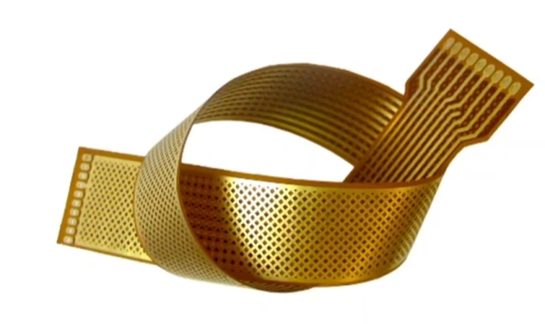
- Grid Pattern Copper Layout: Using a grid pattern for copper layout not only enhances flexibility but also reduces weight. However, it may affect electrical performance and increase manufacturing complexity. Greatpcb will provide a comprehensive assessment to create a reasonable solution.
FPC Routing Design
In rigid PCBs, a 45° angle is often used for routing corners. In FPCs, most manufacturers recommend using curved routing to better relieve stress and tension on the copper layers.
Example of FPC Routing:

FPC Pad Design
Connecting Routing and Pads
Connecting routing directly to pads can create weak points at the connection. During bending, these areas are prone to damage.

To improve connection reliability, it is recommended to add tear-drop designs to enhance the strength of connections between routing and pads, or between routing and vias.

Cover Layer Opening
The cover layer on an FPC functions similarly to a solder mask. Openings are made in the cover layer above the pads. Since flexible circuit boards need to bend during use, the likelihood of pads detaching is significantly higher compared to rigid boards.

A common solution is to add short copper foils extending from the pad connections beyond the cover layer opening. This approach effectively increases pad reliability.

FPC Reinforcement
For certain custom applications where a specific area of the FPC should not be too flexible, a stiffener is required.
What is a Stiffener?
A stiffener is a rigid material added to the FPC to enhance the structural strength of specific areas. It affects the mechanical properties of the FPC without impacting its electrical properties.
Why Use a Stiffener?
- Gold Finger Interfaces: For connections with FPC plug-ins, stiffeners are used to increase thickness and structural strength at the back of gold finger interfaces.
- Component Mounting: When installing components, especially through-hole components, stiffeners are used to enhance the strength of the FPC in that area.
Materials Used for Stiffeners:
1.Polyimide: Polyimide is used in FPC substrates and cover layers and is the most cost-effective stiffener material.

2.Fiberglass (FR4): Commonly used in rigid PCBs, FR4 can provide greater thickness and rigidity.

3.Metal (Aluminum Foil/Stainless Steel): Metal stiffeners not only increase strength but also help with heat dissipation.

Reinforcement and Assembly
Thermal Bonding
Thermal Bonding involves using heat and pressure to bond the stiffener to the FPC. This method offers high-quality and reliable bonding but is more expensive and suitable for applications requiring high adhesive strength and durability.
Pressure-Sensitive Adhesives (PSA)
Pressure-Sensitive Adhesives (PSA) bond when pressure is applied, without the need for heat or solvents. PSA is less expensive compared to thermal bonding and is suitable for general flexible circuit applications.


