Understanding Resonance Frequency Formulas: Series and Parallel Circuits

Overview In digital circuits, both sending and receiving data require a clock reference. Data can be sampled on the rising edge, falling edge, or both the rising and falling edges simultaneously. Common input clock signals are generated by crystal oscillators. In electronics, circuits that contain transistor components are often referred to as “active circuits,” while circuits made only of resistive and capacitive components are called “passive circuits.” Crystal oscillators can be divided into passive and active types. The names for passive and active crystal oscillators differ in English: a passive crystal oscillator is called a “crystal,” while an active crystal oscillator is called an “oscillator.” A crystal requires a clock circuit to generate an oscillating signal; it cannot oscillate on its own. Therefore, the term “passive crystal oscillator” is not entirely accurate. An active crystal oscillator is a complete oscillator, which, in addition to the quartz crystal, includes transistors and resistive-capacitive components, making it larger. The differences in structure between the crystal and the oscillator lead to differences in schematic design.
Crystal Oscillator Working Principle
- Quartz Crystal Characteristics The reason quartz crystals can be used as oscillators is due to their piezoelectric effect: when an electric field is applied across the two poles of the crystal, it causes mechanical deformation. When an alternating voltage is applied, the crystal will vibrate mechanically, and the mechanical deformation will generate an alternating electric field. Although this alternating electric field’s voltage is very weak, its frequency is extremely stable. When the frequency of the applied alternating voltage matches the natural frequency of the crystal (determined by the crystal’s size and shape), the amplitude of the mechanical vibration will increase dramatically. This phenomenon is called “piezoelectric resonance.”
Figure 1: Quartz Crystal Symbol, Equivalent Circuit, and Frequency Characteristics The image from left to right shows the symbol for the quartz crystal, its equivalent circuit, and a schematic of its impedance frequency characteristics. In the equivalent circuit, C0C_0C0 represents the electrostatic capacitance formed by the slice and metal plate. Its size depends on the geometry and electrode area of the crystal and generally ranges from several pF to tens of pF. When the crystal oscillates, the inertia of the mechanical vibration is modeled as an inductor LLL, typically between several mH and hundreds of mH. The elasticity of the crystal is represented as a capacitor CCC, which is very small, generally between 0.0002 to 0.1 pF. The losses due to friction during crystal vibration are represented by a resistor RRR, generally in the range of tens of ohms. Because the equivalent inductance of the crystal is large and CCC is small, the quality factor QQQ of the circuit is very high, ranging from 1000 to 10000. Furthermore, the resonant frequency of the crystal mainly depends on the crystal’s cutting method, geometry, and size, and can be made very precise. Thus, oscillators formed with quartz resonators can achieve high frequency stability.
From the impedance frequency characteristic diagram of the quartz crystal, we can see that quartz crystals have two resonance frequencies:
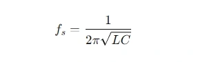
- When the R,L,CR, L, CR,L,C branches undergo series resonance, the series resonance frequency is:
- When the frequency is higher than fsf_sfs but lower than fdf_dfd, the R,L,CR, L, CR,L,C branch becomes inductive. When it resonates in parallel with C0C_0C0, the oscillation frequency is:
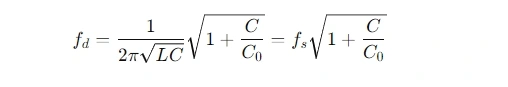
Since C<<C0C << C_0C<<C0, fsf_sfs and fdf_dfd are very close.
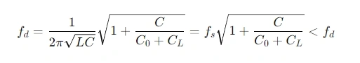
Typically, the nominal frequency provided for quartz crystal products is neither fsf_sfs nor fdf_dfd, but the frequency when a load capacitance CLC_LCL is applied. Since CLC_LCL is in parallel with C0C_0C0, the frequency is:
Thus, quartz crystals oscillate in two modes: parallel resonance and series resonance.
Parallel Resonance
This arrangement places the quartz crystal in parallel resonance mode, and the oscillation frequency is:
A CMOS inverter inside the chip acts as an AB amplifier, providing a 180° phase shift for the input signal, and the combination of the quartz crystal, RSR_SRS, CL1C_L1CL1, and CL2C_L2CL2 forms a π-network that produces another 180° phase shift, completing the 360° phase shift required for oscillation. For stable oscillation, the loop gain must be at least 1. To achieve this, a feedback resistor RfR_fRf is added to the CMOS inverter. This resistor controls the circuit’s gain and ensures that it is suitable for oscillation. If the gain is too high, feedback resistors can limit it to a proper value, typically in the range of 500KΩ to 2MΩ.
RSR_SRS is the current-limiting resistor, preventing the crystal from being overdriven, as excessive power may damage the crystal. CL1C_L1CL1 and CL2C_L2CL2 form the load compensation capacitors, and the total load capacitance CLC_LCL is calculated as:

where CSC_SCS represents the parasitic capacitance from the PCB layout and the crystal leads.
Series Resonance
In this mode, there is no capacitance in the feedback loop. The frequency is given by:
where CSC_SCS is the variable capacitor used to fine-tune the frequency. Under these conditions, the resonance frequency approximates the series resonance frequency.
Quartz Crystal Oscillator Key Parameters
- Load Frequency: The oscillation frequency under a specified load capacitance, indicated on the product package.
- Frequency Tolerance: The allowable deviation from the nominal frequency at the reference temperature (usually 25 ± 3°C), expressed in ppm (parts per million).
- Frequency Stability: The allowable frequency deviation within the specified operating temperature range (e.g., 0~70°C), relative to the reference temperature, also expressed in ppm.
- Aging: The allowable change in frequency over time, typically expressed in ppm per year.
- Shunt Capacitance: The capacitance in parallel with the series branch in the equivalent circuit, denoted as C0C_0C0.
- Load Capacitance: The external capacitance that determines the load resonance frequency, denoted as CLC_LCL.
- ESR (Equivalent Series Resistance): The resistance at the series resonance frequency, provided in the crystal’s datasheet.
- Drive Level: The effective power consumed by the crystal during oscillation.