The 3W Rule in PCB Signal Routing

Importance of Sufficient Separation in High-Frequency Signal Routing
Signal routing on a PCB, especially for high-frequency digital signals, requires sufficient separation to minimize crosstalk. When the center-to-center spacing between traces is no less than three times the trace width (with edge-to-edge spacing being twice the width), 70% of the electromagnetic fields do not interfere with each other. This is commonly known as the 3W rule.
Reliability of the 3W Rule
The 3W rule is generally reliable, as the strength of the electromagnetic field decreases with the square of the distance, a principle that is always valid. The farther apart the traces, the less the crosstalk. However, in reality, there is often limited space available on a PCB.

Application and Limitations of the 3W Rule
In complex electromagnetic environments, design requires careful consideration and balance of various factors. Therefore, while applying the 3W rule, several key points must be noted. First, not all routing on a PCB must strictly adhere to the 3W rule. It is typically applied to high-speed signal lines where long-distance routing is involved, such as clock lines, high-speed data lines, video and audio signal lines, and reset signal lines.
Influence of PCB Stack-Up on Crosstalk
Crosstalk between signal lines is not only influenced by spacing but also by the PCB stack-up. For instance, in a 4-layer PCB with routing and reference layers separated by 5-10 mils, the 3W spacing is sufficient. However, in a 2-layer PCB where the separation between routing and reference layers is 45-55 mils, the 3W spacing may not be adequate for high-speed routing.
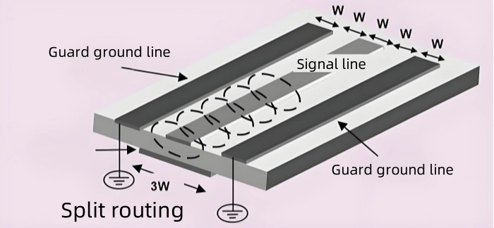
Additional Measures for Crosstalk Prevention
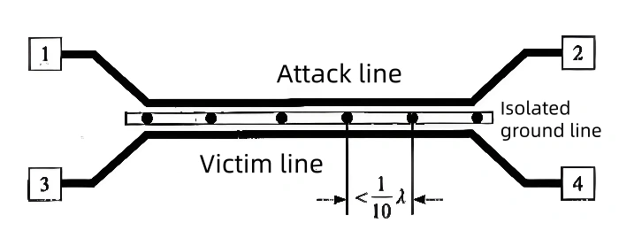
If the 3W spacing is applied but still does not meet crosstalk prevention requirements, additional measures are necessary. These may include adding guard traces on both sides of the signal line, placing split routing in the vertical direction, or adding ground lines between data lines to isolate them.
Ground lines should be placed according to signal frequency, with spacing no greater than 1/10 λ.
Applicability of the 3W Rule for Controlled Impedance Lines
The 3W rule is suitable for ordinary single-ended signal lines and their spacing from other traces. For controlled impedance signal lines, the simple 3W rule does not apply, as many factors influence trace impedance. Electromagnetic field solvers may be needed for analysis. For example, the impedance of differential pairs is affected not only by spacing but also by the dielectric thickness, the distance between traces and reference layers, the dielectric constant, copper thickness, and other factors.

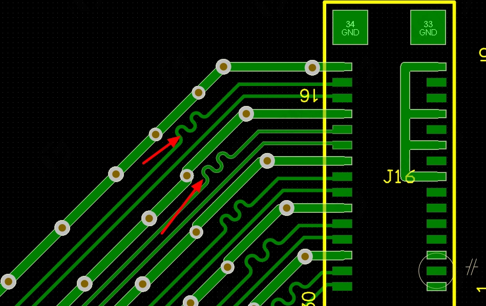
The 3W Rule for Serpentine Routing
Except in thin dielectric layers, where the impedance of a 50-ohm stripline is approximately 3W apart, other impedance traces often require some coupling between the two traces, so the spacing is often less than 3W. The precise value needs to be calculated using an impedance calculator. For high-speed differential pairs, the spacing may need to exceed 5W, as seen in USB 2.0 high-speed differential pairs. Lastly, it is worth noting another version of the 3W rule, which applies to serpentine routing. When matching signal lengths with serpentine traces, to prevent significant impedance changes, the length of the serpentine segment should be less than 3W, as shown in the diagram below.
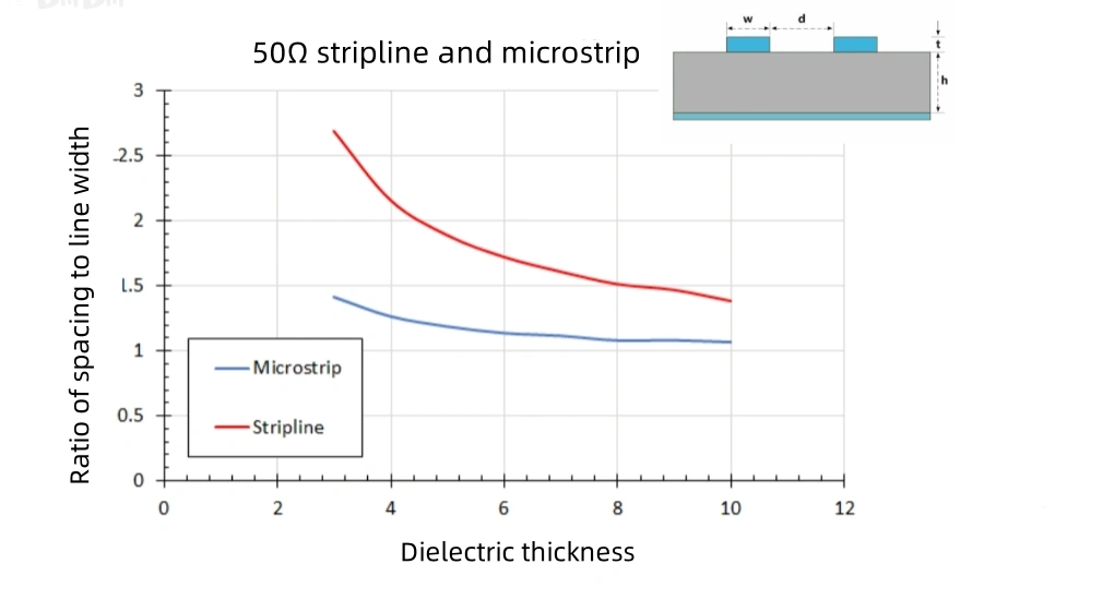

Table of Contents

Related Posts
PCBA Prototype
July 21, 2026
PCBA Prototype
July 17, 2026