
Medical PCB Assembly
GreatPCB provides PCB fabrication, component sourcing and assembly for medical electronics projects, from prototypes to repeat production. Our services include SMT and through-hole assembly, IC programming, inspection, testing and conformal coating, with the manufacturing scope defined around your design and quality requirements.
Send your Gerber files, BOM and build quantity to discuss the next steps. If your project has specific cleaning, traceability or acceptance requirements, include them early so they can be considered alongside the board construction and assembly process.
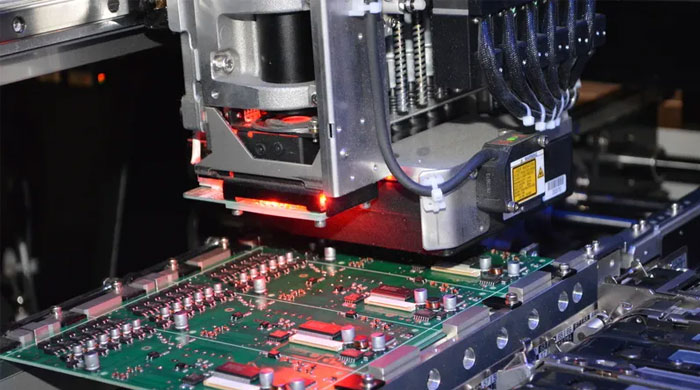
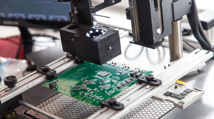
SMT assembly · illustrative third-party image.
to repeat production
Medical Applications
Medical electronics combine different manufacturing challenges. A compact monitoring board may need dense component placement, while a diagnostic instrument may combine sensitive measurement circuits with power and control electronics.
These categories are a starting point for reviewing your board. The intended use, operating environment and product requirements determine which construction, protection and verification steps are needed.
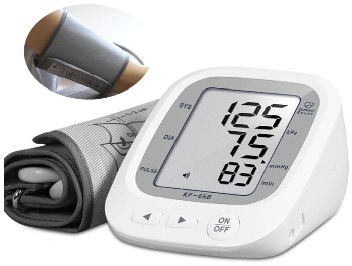
Patient monitoring
Sensor interfaces, component accuracy, signal-path cleanliness and defined electrical checks
Diagnostic instruments
Mixed analog and digital circuitry, thermal management, connector assembly and test access
Portable medical electronics
Compact layouts, battery connections, fine-pitch components and enclosure fit
Equipment control boards
Power devices, through-hole connectors, programming and verification of control functions
Manufacturing and Assembly
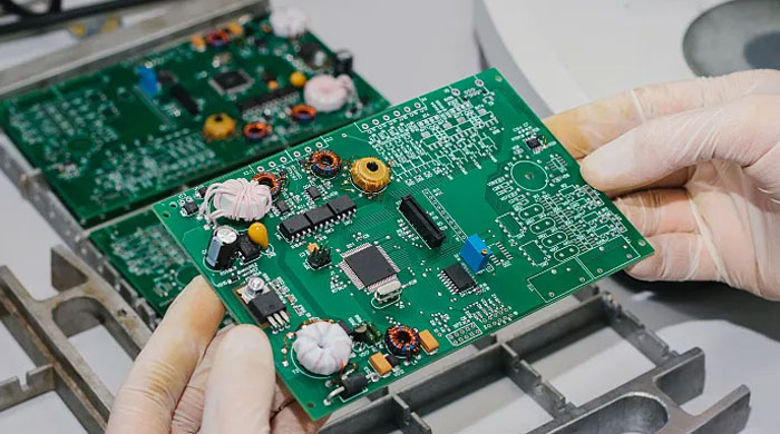
PCB Fabrication and DFM
Manufacturing starts with a consistent set of design files. The PCB drawing, layer stackup, drill data and Gerber files should identify the same revision and define the material, copper, surface finish and electrical requirements.
DFM review helps identify issues before fabrication: fine-pitch pad geometry, via treatment, board clearances, panel handling and access for assembly or testing. For multilayer, HDI or rigid-flex designs, the construction must also suit the component layout and available manufacturing process. Choosing a more complex board technology is useful when it solves a specific routing, space or interconnection problem.
Component Sourcing and Assembly
With component sourcing, the BOM should specify manufacturer part numbers, package details and approved alternatives. An available part with a similar description may still differ in electrical behavior, thermal limits or firmware compatibility. Replacement parts therefore need approval against the design requirements before use.
SMT and through-hole processes can be combined for boards containing fine-pitch ICs, power components and connectors. For BGA assembly, pad and via construction, the thermal process and inspection access need to be considered together. Hidden joints make it particularly important to address fabrication and assembly risks before production.
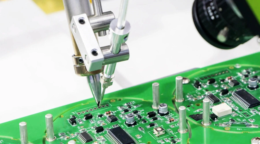
Prototype to Production
A prototype build is an opportunity to check assembly fit, component orientation, programming and the proposed test procedure. Findings should be resolved in a released manufacturing package before the next build.
For repeat production, keep the approved PCB revision, BOM, assembly instructions, firmware and test limits aligned. If a component or process changes, assess the effect on existing stock and work in progress as well as future orders. This helps prevent a successful prototype from being followed by a production batch built to a different combination of files.
Quality Control
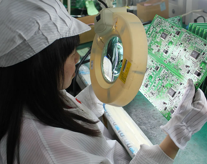
Visual inspection · illustrative third-party image.
Components and Process Control
Incoming checks establish whether the PCB and components match the purchase and build requirements. Relevant checks can include identification, package condition, visible damage and specified documentation. Component handling should follow the device supplier’s moisture-sensitivity and ESD requirements; a single storage or baking recipe does not suit every package.
During assembly, solder-paste printing, placement and the thermal process each affect the finished joint. First-article checks help confirm the setup before continuing the build. Where the board contains parts with different thermal demands, the reflow profile needs to account for the actual assembly rather than relying only on an oven setting.
Cleaning and Protection
PCBA cleanliness concerns electrical performance as well as appearance. Moisture and ionic contamination can reduce insulation resistance and create leakage paths. Residues can also interfere with coating adhesion, as explained in ZESTRON’s PCB cleaning guidance.
The cleaning decision should consider the flux, component spacing, operating environment and any subsequent coating. A no-clean flux designation alone does not settle whether residues are acceptable for a particular assembly.
A visually clean surface does not establish electrical cleanliness beneath components. Where cleanliness verification is required, agree the assessment method and acceptance criteria for the assembly.
If cleaning is required, the chemistry and process must suit the PCB, components, markings and connectors. Rinsing and drying matter alongside residue removal, especially where liquid can remain under components. Conformal coating also needs defined coverage and keep-out areas. Neither board cleaning nor coating establishes that a finished medical device is sterile.
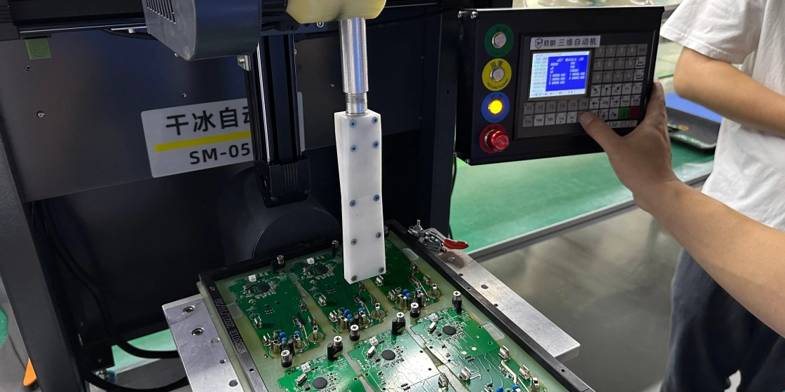
Existing page image. Cleaning compatibility is reviewed for the assembly.
Inspection and Testing
Inspection and electrical testing answer different questions. The plan should identify the features to check, the acceptance criteria and any fixtures, software or reference samples needed.
SPI and AOI: Check solder-paste deposition or visible assembly features, depending on the equipment and inspection program.
X-ray inspection: Examines otherwise hidden solder features, including those beneath BGA packages. The image and viewing method limit what can be concluded.
Electrical testing: Checks specified connections or circuit parameters within the available test access.
Functional testing: Runs defined operating checks using the agreed firmware, inputs, loads and pass/fail limits.
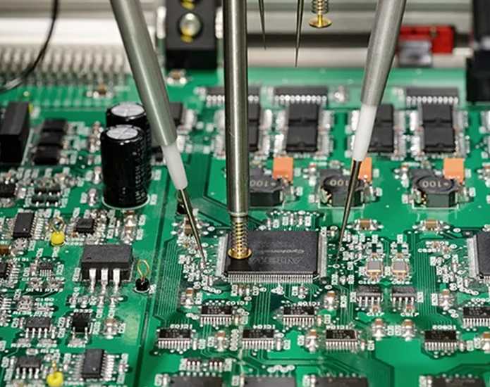
Electrical probing · illustrative third-party image.
A board can pass visual inspection and still have a functional fault. Conversely, a short functional check may not reveal a hidden joint problem. Combining methods should follow the board’s risks and required coverage, rather than applying the same test list to every medical PCBA.
Acceptance requirements should distinguish bare-board performance, assembly workmanship and product function. The FDA’s medical-device risk classes are a separate classification from IPC product classes; the assembly acceptance class and applicable documents need to be specified for the project.
If your supplier-qualification process requires ISO 13485 certification, confirm the certificate holder, manufacturing site and scope during supplier review. Certification requirements and board-level acceptance criteria should both be addressed before the build.
Traceability and Change Control
Traceability connects an assembly to the materials, revisions and production records relevant to its build. Agree the required detail before production, including whether identification is by batch or individual board and which records must accompany delivery. The published IPC-1782 scope treats manufacturing and supply-chain traceability in terms of risk and agreement between user and supplier.
| Record to define | Purpose |
|---|---|
| PCB part number, revision and production lot | Identify the board construction used in the build |
| Component identification and required lot/date-code records | Connect selected materials to the relevant assembly batch |
| Assembly and programming revisions | Establish which instructions and firmware were released |
| Inspection, test and rework records | Document the checks performed and disposition of affected boards |
Change control keeps these records meaningful. A component substitution or firmware update should have an approval, an effective revision or batch, and instructions for affected material or assemblies. Record retention, report format and access requirements should be included in the project agreement.
What Do You Need for a Medical PCBA Project?
The following information helps define the manufacturing scope and identify questions before a build starts.
You can begin with the files you already have. Share any known gaps or pending decisions so the remaining inputs can be identified before production.
| Information | What to include |
|---|---|
| PCB fabrication package | Gerber and drill files, fabrication drawing, stackup, material and finish requirements |
| Component information | BOM with manufacturer part numbers, approved alternatives and any customer-supplied parts |
| Assembly package | Pick-and-place file, assembly drawings, polarity notes and mechanical constraints |
| Build plan | Quantity, released revision, prototype or repeat-production status, and required delivery date |
| Quality requirements | Acceptance documents/class, cleaning or coating requirements, and relevant operating conditions |
| Programming and testing | Released firmware, configuration instructions, test procedure, fixtures and pass/fail limits |
| Delivery records | Required identification, traceability depth, inspection reports and packaging instructions |
Discuss Your Project
Send your design files, BOM and quantity to discuss medical PCB assembly with GreatPCB.