Electrolytic Capacitor Failure: Causes, Lifespan & Cases
Fault Case
I recently repaired one of a customer’s devices. The problem was that the switch-mode power supply module had a strange fault. I tested it with a multimeter. The 5V output was normal, but the 12V output jumped to 20V.
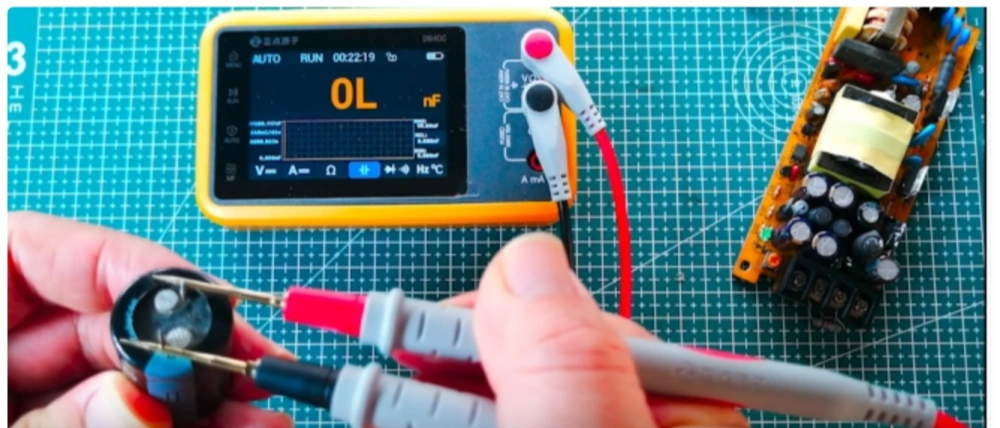
After opening it up and checking, I found that the rectifier filter capacitor had aged. It had almost no capacitance left. This caused a very large ripple after rectification, and the voltage regulation loop of the switching power supply became confused.
The fix was very simple. Replacing the capacitor would make it work again. But this power module could no longer be used, because you could not be sure how long the other capacitors, resistors, and parts could still last. The only safe choice was to replace the whole power module with a new one.
The Problem Engineers Fear Most: Component Failure
The power failure in the device above was clearly caused by electrolytic capacitor failure. This problem stopped the customer’s product from running for several days, and the loss was easy to see. So component failure is an important topic that product engineers should pay close attention to and study carefully.
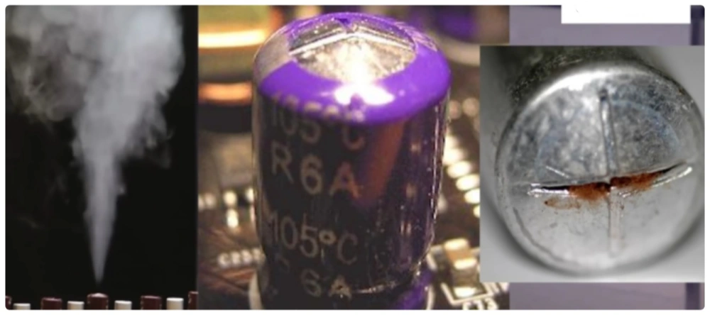
When it comes to electrolytic capacitor failure, anyone who repairs circuits often is very familiar with it: lower capacitance, leakage, swelling, and so on. Leaked electrolyte can spread everywhere and make the circuit stop working normally. Electrolytic capacitors are also used most often in power supplies. When they fail, the power supply becomes abnormal, and the loss is often much greater than the value of one or two capacitors.
Why Do Electrolytic Capacitors Fail?
Reason 1: Overvoltage Breaks Down the Oxide Layer
So what causes capacitor failure? One common reason is that the capacitor is made to handle a voltage higher than its rated value. For example, the electrolytic capacitor is connected with reversed polarity, or a 6.3V electrolytic capacitor is used on a 12V power supply. Anyone who does PCBA design knows that few people have never blown up a capacitor before.
Even a short overvoltage can break down the oxide layer of the aluminum foil and create a short circuit inside the capacitor.
Reason 2: Ripple Current Is Too High
The second reason is too much ripple current. Electrolytic capacitors are usually used in power circuits to filter ripple current, but excessive ripple current will generate heat inside the capacitor. This makes the electrolyte evaporate and increases the pressure inside the capacitor. This can speed up aging, which can lead to swelling, leakage, and even explosion.
Reason 3: Working Temperature Is Too High or Too Low
The third reason is an abnormal working temperature.
A high working temperature is the easiest to ignore, and it is also one of the most important reasons for early capacitor failure. High temperature speeds up electrolyte evaporation, lowers capacitance, and increases equivalent series resistance (ESR). A temperature that is too low is also bad. Low temperature can make the electrolyte solidify, greatly reduce capacitance, and noticeably increase series resistance.
Reason 4: Natural Material Aging
There are also other reasons. For example, the materials in the electrolytic capacitor will age over time. This aging process can be made faster by environmental factors like humidity and temperature. The result is gradual performance loss and, in the end, complete failure.
Advantages and Disadvantages of Electrolytic Capacitors
In general, electrolytic capacitors have large capacitance and low cost, so they are necessary parts in power circuits. But we also need to know that their disadvantages are very clear. They do not last long, and they are very sensitive to working temperature. If they work in high temperature for a long time, they may not reach the expected service life.
Electrolytic Capacitor Life and Temperature
The expected life of an electrolytic capacitor can be estimated with an empirical formula:
Simplified formula:
f1 = 2(ΔT/10)
LB is the base life, usually 1000 to 2000 hours. f1 and f2 are functions related to temperature and working voltage. TM is the maximum working temperature, usually 105°C. TC is the capacitor’s working temperature. Here, f1 is an exponential function with base 2.
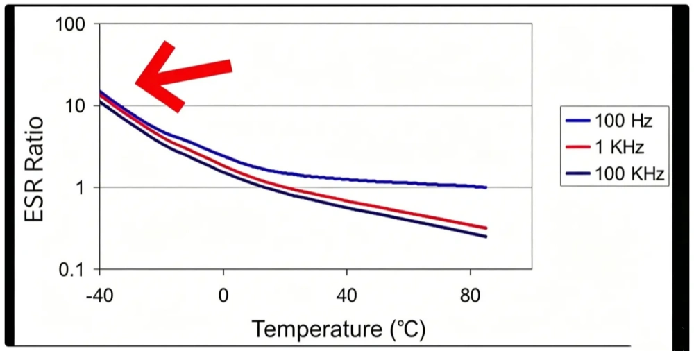
This empirical formula tells us that every 10°C rise in temperature cuts capacitor life in half. When the temperature is below -25°C, the performance of an electrolytic capacitor also gets much worse. For example, at -40°C ambient temperature, ESR can be 10 times higher than at room temperature.
So keeping the capacitor within the right working temperature is very important. In general, if you want the capacitor life to be more than 2500 hours, the working temperature TC must be below 65°C. This is not easy for some sealed products, switch-mode power supplies, chargers, and LED lamps.
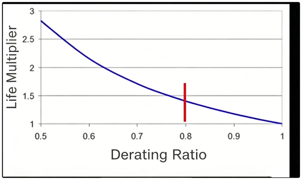
Can Derating Improve Capacitor Life?
Another main way to reduce electrolytic capacitor failure is derating. For example, a capacitor with a 16V rating may be derated by 80% and used in a 12V circuit.
But note that derating does not clearly improve life. The reason is that a high-voltage capacitor, after its working voltage is reduced, may still have higher ESR than a low-voltage capacitor. Higher ESR means higher working temperature, and this will finally shorten life.
A Failure Case Involving Tantalum Capacitors
I also have another painful experience to share about capacitor failure: be careful with tantalum capacitors, because their failure is very severe. In mild cases they explode. In serious cases they catch fire.
I once had a batch of circuit boards where one tantalum capacitor failed and burned. It even burned through the PCB. The circuit board becoming useless was not the biggest problem. The damaged PCB caused the power supply regulation loop to collapse, and it directly killed the precision sensor connected to it. The loss was tens of thousands of dollars.
Note on Tantalum Capacitor Types
There is one more point to add here, so there is no misunderstanding. The failure case above does not mean that all tantalum capacitors have the same problem.
In fact, electrolytic capacitors include many different types, such as aluminum electrolytic capacitors, conductive polymer aluminum solid electrolytic capacitors, and conductive polymer hybrid aluminum electrolytic capacitors. Tantalum capacitors also have different technical types:
- Traditional manganese dioxide tantalum capacitors (MnO₂ Tantalum)
- Conductive polymer tantalum capacitors (Polymer Tantalum)
Their electrical performance, life characteristics, and failure modes are clearly different, and some are very different.
Many technical articles simply say, “tantalum capacitors have low ESR.” This is not very strict. For the same capacitance and voltage rating, the ESR at 100 kHz of manganese dioxide tantalum capacitors and conductive polymer tantalum capacitors may differ by dozens or even hundreds of times.
In the same way, it is not correct to treat all electrolytic capacitors as one kind of part, or to treat all tantalum capacitors as having the same features. Products with different technical types can have completely different reliability, ripple resistance, ESR, temperature behavior, and failure mechanisms.
So when analyzing component failure, you should not only look at the words “electrolytic capacitor” or “tantalum capacitor.” You also need to check which specific technology is used, and whether the working conditions meet the design requirements.
Besides Capacitors, Also Pay Attention to Other Component Failures
So for tantalum capacitors, you should not simply say they are “good” or “bad.” During design, you need to choose them based on the exact type, working environment, and reliability needs. If you use traditional manganese dioxide tantalum capacitors, you should pay special attention to inrush current and derating design. If you use polymer tantalum capacitors, you should focus on ripple handling, leakage current, and long-term reliability.
Besides capacitors, resistor failure is also something you often see. If you want your developed product to stop worrying you, you should study the failure modes of all parts carefully, including capacitors, resistors, and semiconductor devices.
FAQ
One possible failure mode is short circuit, and that cannot be solved just by replacing it with several parts. It also increases cost and takes up more board area. Also, after the capacitance drops, the zero-pole pair formed by the power devices will change, and the loop may no longer stay stable.
A life of a few thousand hours is the rated life under full load. For example, a capacitor rated at 105°C for 2000 hours can reach 32,000 hours at 65°C with medium ripple. That means about 3.5 years of continuous use, and even longer under conservative use.
Companies like TDK and Vishay provide calculators and charts to estimate the actual Useful Time. Also, “life” can be measured in many ways. These are all statistical values, such as MTBF and DMTBF.
Tantalum capacitors are also a kind of “electrolytic capacitor.” They have large capacitance in a small size, but they do not contain liquid electrolyte, so they do not dry out or leak. They also have a weak self-healing feature, which can also be one reason why their failure can be severe.
Compared with MLCCs, tantalum capacitors have a positive temperature characteristic. Their ESR is higher than MLCCs, but their frequency curve is flatter.
Table of Contents

Related Posts
PCBA Prototype
July 10, 2026