Tips for High-Power PCB Design: Heat Management & Safety

1. What is High-Power PCB?
High-power PCB is a printed circuit board made of heavy copper. Compared to other circuit boards, high-power PCBs can handle higher current rates, withstand high temperatures for extended periods, and provide robust connection points.
High-Power PCB Features
Designing a high-power PCB for specific devices requires higher amounts of current and is often subjected to fluctuating temperatures.
To function effectively, high-power PCB designs include the following features: the copper layers in high-power PCBs are thicker and heavier compared to those in other PCBs, enabling them to conduct higher currents.
Heat Transfer in PCBs
The ability to conduct higher currents combined with heat dissipation helps ensure that devices made from PCBs won’t short-circuit during operation. Due to these features, high-power PCBs can resist and adapt to the fluctuating temperatures of devices in use.
2. Types of High-Power PCB Designs
There are many types of high-power PCBs available on the market, and here are three common classification standards:
1. Double-Sided High-Power PCB
These are high-power printed circuit boards that allow components to be mounted on both sides. This is the entry-level product made using high-power PCB technology.
By using vias and alternating traces between the top and bottom layers, they are more efficient and reliable compared to single-sided high-power PCBs.
2. Rigid-Flex High-Power PCB Design
High-power printed circuits are made from a combination of rigid and flexible substrates. Typically, rigid-flex high-power boards consist of multiple layers of flexible substrates, which are then connected to one or more rigid boards.
These connections are made either internally or externally, and the expected applications of high-power rigid-flex boards are crucial in determining how the connections are completed.
Moreover, flexible components are designed to remain flexible at all times, which is useful in corners and areas requiring additional space. Rigid substrates provide support in areas that need extra strength.
With these features, it is ensured that these high-power rigid-flex boards can be bent during the manufacturing and installation process. Rigid-flex technology allows high-power PCBs to adapt to smaller applications, enhancing performance and convenience.

3. Multi-layer High-Power PCB Design
Multi-layer high-power circuit boards have at least three conductive layers. The most common electrical connection strategy in these boards is the use of plated through holes (PTHs).
Depending on the intended purpose of the PCB, the conductive layers can go up to twelve layers. However, some companies are now manufacturing PCBs with as many as 100 layers, providing space for some of the most complex high-power PCB applications.
3. Advantages of High-Power PCB Design
- Increased Thermal Strain Tolerance
- The thick copper in high-power PCBs enables them to withstand thermal stress. As a result, devices made from high-power PCBs can resist temperature fluctuations, making them reliable and commonly used in military applications.
- Increased Current Carrying Capacity
Heavy copper also enables high-power PCBs to conduct large currents without excessive strain. High-current circuits on lighter copper PCBs are prone to failure and malfunction.
Devices like power transformers are exposed to very high currents, and without high-power PCBs, they are likely to fail or trigger circuit disasters.
- Increased Mechanical Strength at Connector Points and PTH Holes
Heavy copper used in high-power PCBs gives them mechanical strength, which is vital for supporting components mounted on the board. The connector points in high-power PCBs are reinforced, extending to PTH holes, which are also made of copper. - Reduced Product Size
High-power PCB designs help reduce product size by combining multiple copper weights in the same layer of the circuit, explaining their preference in military applications, where most products need to be portable. - Thermal Transfer to External Heat Sinks
By using thick copper-plated PTHs, high-current conduction is enabled through the PCB. This helps transfer heat to external heat sinks, making high-power PCBs highly effective in applications that require high current to operate.
The heat sinks in high-power PCB designs can also be directly plated onto the board, which is why high-power PCBs are often used in industrial settings.
4. High-Power PCB Design Tips
Consider Safety
As with any circuit, the primary concern for high-current circuits is ensuring safe operation. A circuit board designed to drive high-power loads has some unique potential issues, with heat being the primary concern. No matter how you design and lay out the PCB, more heat will be generated compared to standard PCBs.
This must always be taken into account when designing enclosures, and external vents/fans should be used. One useful measure for designs that drive more than a few amperes is to install a dedicated temperature sensor on the PCB. This is a great firmware-based fault protection. With the ability to monitor temperature, you should always be able to respond to any overheating situation. To reduce the heat generated by the PCB itself, it’s best to choose components with low resistance.
The next potential safety concern is related to short circuits. Since this board is designed to drive high-power devices, it will be able to provide significant current in the event of a short circuit. It’s crucial to consider this possibility during the design stage. The simplest way to deal with short circuits is to install a fuse on all outputs leaving the board, as well as an input fuse. The fuse rating should always be lower than the current the wiring can handle, and the current rating should be less than or equal to the amount of current the PCB traces/encapsulation can support. Using drivers with built-in short circuit protection is also a good idea.
PCB Power Design
Establishing the power path is one of the most important rules for high-power PCB circuits. This determines where and how much power should flow through the circuit, as well as the positioning of ICs and the required heat dissipation for the PCB.
Several factors influence the layout of the design:
- The amount of current flowing through the circuit
- The ambient temperature of the equipment and PCB design
- The expected airflow around the equipment or PCB
- The material used for the PCB
- The IC density of the PCB
PCB Layout
PCB layout should be considered from the early stages of development. An important rule for any high-power PCB is determining the power path. The amount and location of the power flowing through the circuit are crucial factors for evaluating how much heat the PCB needs to dissipate. The main factors influencing PCB layout include:
- Power level flowing through the circuit
- The working ambient temperature of the PCB
- The airflow affecting the PCB
- The material used to manufacture the PCB
- The component density on the PCB
It’s generally a good practice to divide the PCB into low-power and high-power sections. This ensures that high-power traces are as close as possible to the power and output. The board will be 2-layer with 2oz copper.
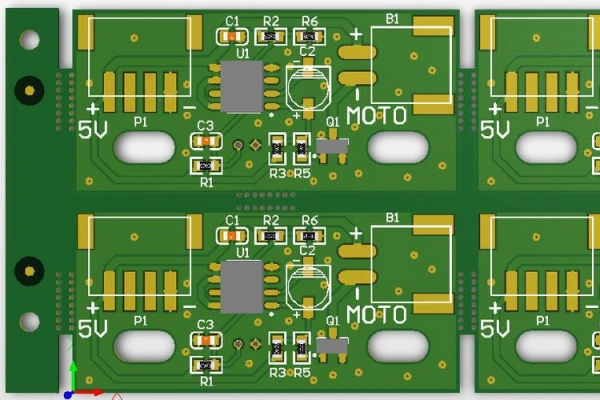
When designing high-current PCBs, one approach is to create a rough initial layout, with traces as thin as 8 mils, to ensure components are placed optimally. This helps in visualizing the exact path for high-current traces and how best to position the H-bridge driver.
The image below shows the initial layout of components with 8 mil traces for defining the final trace paths. The power enters through the bottom terminal, goes through an input fuse, branches to the H-bridge driver, and the low-current power rises to the 5V regulator in the center of the PCB.
Component Selection
High-current designs and power systems often rely heavily on the components for reliability. While this may seem obvious, ensure the safety margin is considered when selecting components. Generally, it’s best to start by reviewing two key specifications:
- Rated current, especially for MOSFETs and inductive components
- Thermal resistance
If available, you can use the estimated or designed operating current to calculate power dissipation, or use the first specification to get the worst-case value. Both will help with thermal management, which requires using thermal resistance values to estimate temperature. For some components, determining whether heat sinks are necessary can ensure reliability.
Other components critical for high-current PCBs, such as connectors, may have very high ratings and can be quite useful in power systems. The image below shows examples of mechanical screw terminal connectors that can handle very high currents.
Proper Copper Weight
The copper resistance in traces leads to some DC power loss, which dissipates as heat. This becomes very important for designs with very high currents, especially when component density is high.
The only way to prevent DC loss in high-current PCBs is to use copper with a larger cross-sectional area. This means using heavier copper or wider traces to keep Joule heating and power loss sufficiently low.
Use a PCB trace width vs current chart to determine the required copper weight or trace width to prevent excessive temperature rise.
Grounding
A high-power PCB system requires the use of the same safety measures. A proper grounding strategy provides a certain level of safety and EMI protection. Typically, grounding should not be separated, but power systems involving high currents and/or voltages are an exception. Grounding needs to be separated between AC inputs, non-regulated DC, and regulated DC parts.
A good starting point is the grounding strategies you can find in AC systems or isolated power supplies. Usually, for high-current power systems, you’ll use a 3-wire DC setup (PWR, COM, GND), where the GND connection is the actual ground connection. Your PCB might use an isolation strategy where the output side is disconnected from GND, and the input side is grounded to ensure safety in the event of a failure.
Component Placement
It’s crucial to determine where high-power components, like voltage converters or power transistors, will be placed on the PCB. These components generate significant amounts of heat.
Power components should not be placed near the edges of the board, as this can cause heat buildup and significant temperature rise. Highly integrated digital components, such as microcontrollers, processors, and FPGAs, should be positioned at the center of the PCB to ensure uniform heat dissipation across the entire board, thereby lowering temperature. Power components should never be concentrated in the same area to avoid hotspots. Instead, linear arrangements are preferred. The image below shows thermal analysis of an electronic circuit, highlighting the highest thermal concentration areas in red.
Layout should start with the power devices, with traces as short and wide as possible to eliminate noise generation and unnecessary grounding loops. In general, the following rules apply:
- Identify and reduce current loops, especially high-current paths.
- Minimize resistance voltage drop and other parasitic phenomena between components.
- Keep high-power circuits away from sensitive circuits.
- Employ good grounding measures.
Besides the above layout considerations, avoid mixing different power components on the board. For thermal balance, ensure these heat-generating components are evenly distributed across the PCB.
This will effectively protect the PCB from warping, ensuring reduced heat buildup and safeguarding sensitive circuits. Signal integrity will also be equally protected during operation.
IC and Component Mounting
Whenever there is power flow in a circuit, all components will generate heat. When passive components and ICs generate heat, it will likely dissipate into the surrounding cooler air.
This dissipation occurs through the device’s lead frame or packaging. Therefore, most IC packages are not designed to leave much room for external heat sinks.
Additionally, a method for extracting heat from the device is required. Exposed pads are one such method. For optimal thermal performance, use bare die inside the package.
The package should have an EP (Exposed Pad) directly connected to it. ICs should then be correctly mounted on the board, optimizing the heat transfer from the package to the PCB.
Heat Sinks
The goal of using heat dissipation is to prevent heat from being absorbed into surrounding copper during soldering. For many high-power PCB designs, thick copper is often used for manual soldering. Even on 2 oz copper, it can quickly handle solid pads. I prefer using heat sinks on all non-power networks and firm connections on power networks.
Trace Thickness and Width
When designing any PCB, you need to know the minimum trace width. This becomes crucial for high-power PCBs.
In principle, the longer the trace, the higher its resistance and the greater the heat dissipation. Since the goal is to minimize power loss, it’s recommended to make the high-current traces as short as possible to ensure high reliability and durability. To correctly calculate the trace width, knowing the maximum current it can carry, designers can rely on the formula included in IPC-2221 standards or use online calculators.
As for trace thickness, typical values for inner layers of standard PCBs are around 17.5 µm (1/2 oz/ft²), and for outer layers and ground planes, it’s about 35 µm (1 oz/ft²). High-power PCBs usually use thicker copper to reduce the width of traces carrying the same current, saving space on the PCB.
Thicker copper thickness ranges from 35 to 105 µm (1 to 3 oz/ft²), typically used for currents above 10 A. Thicker copper inevitably increases costs but helps save space on the PCB as the viscosity is higher, reducing the required trace width.
Solder Mask
Another technique that allows traces to carry large currents is removing the solder mask from the PCB. This exposes the underlying copper material, which can then be augmented with additional solder to increase the copper thickness and reduce the overall resistance of the PCB’s current-carrying components. While this may be considered a workaround rather than a design rule, this technique allows the PCB traces to carry greater power without increasing the trace width.
Decoupling Capacitors
When a power rail is shared between multiple components on the PCB, active components may generate harmful phenomena like ground bounce and ringing, leading to voltage drops at the power pins of components.
To overcome this issue, decoupling capacitors are used: One terminal of the capacitor should be connected to the power rail, while the other terminal should be grounded. These capacitors eliminate power spikes on the PCB to avoid failure when running high-current devices.
Table of Contents

Related Posts
PCBA Prototype
July 10, 2026