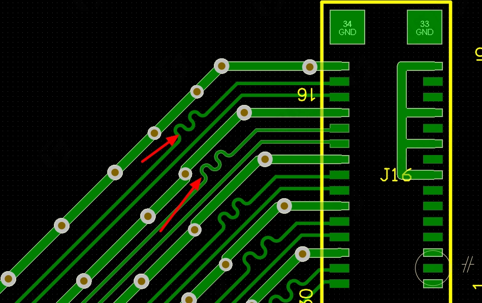
The Role and Considerations of Serpentine Traces in PCB Design

Any trace on a PCB that carries high-frequency signals can cause signal delay. The main purpose of serpentine traces is to compensate for parts of a group of related signals that experience less delay. These parts usually go through fewer or no additional logic processing steps. The most typical example is the clock line, which often bypasses other logic processing and thus has less delay compared to other related signals.
What are Serpentine Traces Used For?
Serpentine traces serve various functions depending on the needs of the PCB. Some of the key functions include:
- Delay Compensation: The primary function is to compensate for parts of related signal lines that have less delay due to bypassing additional logic processing. A common application is the clock line, which usually doesn’t require logic processing, leading to less delay than other signals.
- Antenna Function: This trace design is often seen in devices like mobile phones and radios because some antennas are implemented using serpentine traces on the PCB.
- Filtering: In RF circuits, serpentine traces can form an LC circuit, which can filter signals of certain frequencies.
- Fuse: Short and narrow serpentine traces can be used as fuses.
- Other Uses: In different applications, serpentine traces can serve various roles. On a computer motherboard, for example, they act as inductors for filtering and improve the circuit’s interference resistance. They can also be used for clock signals such as PCICLK and AGPCLK, serving functions like impedance matching and filtering.

High-Speed Digital PCB Design
In high-speed digital PCBs, matching the length of traces ensures that the delay differences between signals remain within a specified range, ensuring the validity of data read within the same clock cycle. If the delay exceeds one clock cycle, it may result in reading the next cycle’s data, leading to errors. Typically, the delay difference should not exceed 1/4 of the clock cycle. The delay per unit length is constant and depends on factors such as trace width, length, copper thickness, and board structure. However, longer traces increase distributed capacitance and inductance, which can degrade signal quality.
Serpentine traces are often not intended to act as inductors because inductance can cause phase shifts in higher harmonics, worsening signal quality. As a result, serpentine traces are spaced at least twice the trace width apart. The smaller the signal rise time, the more it is affected by distributed capacitance and inductance. Serpentine traces in different applications can serve various roles, such as filtering inductors in computer boards or impedance matching and filtering inductors in clock signals on motherboards.
For example, in Intel Hub Architecture, the 13 signal lines running at 233 MHz must be of equal length to eliminate timing hazards. Serpentine routing is the only solution to meet this requirement. Typically, the spacing between serpentine traces is at least twice the trace width, as seen in PCI boards, where serpentine traces are used to meet the length requirements for the 33 MHz PCI clock. In general PCB designs, serpentine traces can act as distributed LC filters, inductors for radio antennas, or even fuses if short and narrow.
Key Considerations for Serpentine Traces
- Maximize Parallel Line Spacing: Increase the distance between parallel sections of the serpentine trace (S), which should be greater than 3H, where H is the distance between the signal trace and the reference plane.
- Minimize Coupling Length (Lp): Keep the length of coupling between traces as short as possible.
- Use Stripline or Buried Microstrip Designs: These designs produce less signal delay in serpentine traces.
- Avoid Serpentine Traces on High-Speed Lines: Especially avoid small, tight curves on high-speed signals.
- Use Arbitrary Angles: If space allows, arbitrary angles in serpentine traces can reduce coupling.
- Serpentine Traces in High-Speed PCB Design: These traces are used only for timing matching and do not offer filtering or anti-interference functions.
- Consider Spiral Routing: In some cases, spiral traces may offer better performance than serpentine traces.
- Use 45° or Rounded Corners: The corners of serpentine traces should use 45° angles or rounded corners.

By adhering to these guidelines, serpentine traces can be effectively used to manage signal timing and other functions in PCB designs.
Table of Contents

Related Posts
PCBA Prototype
July 21, 2026
PCBA Prototype
July 17, 2026