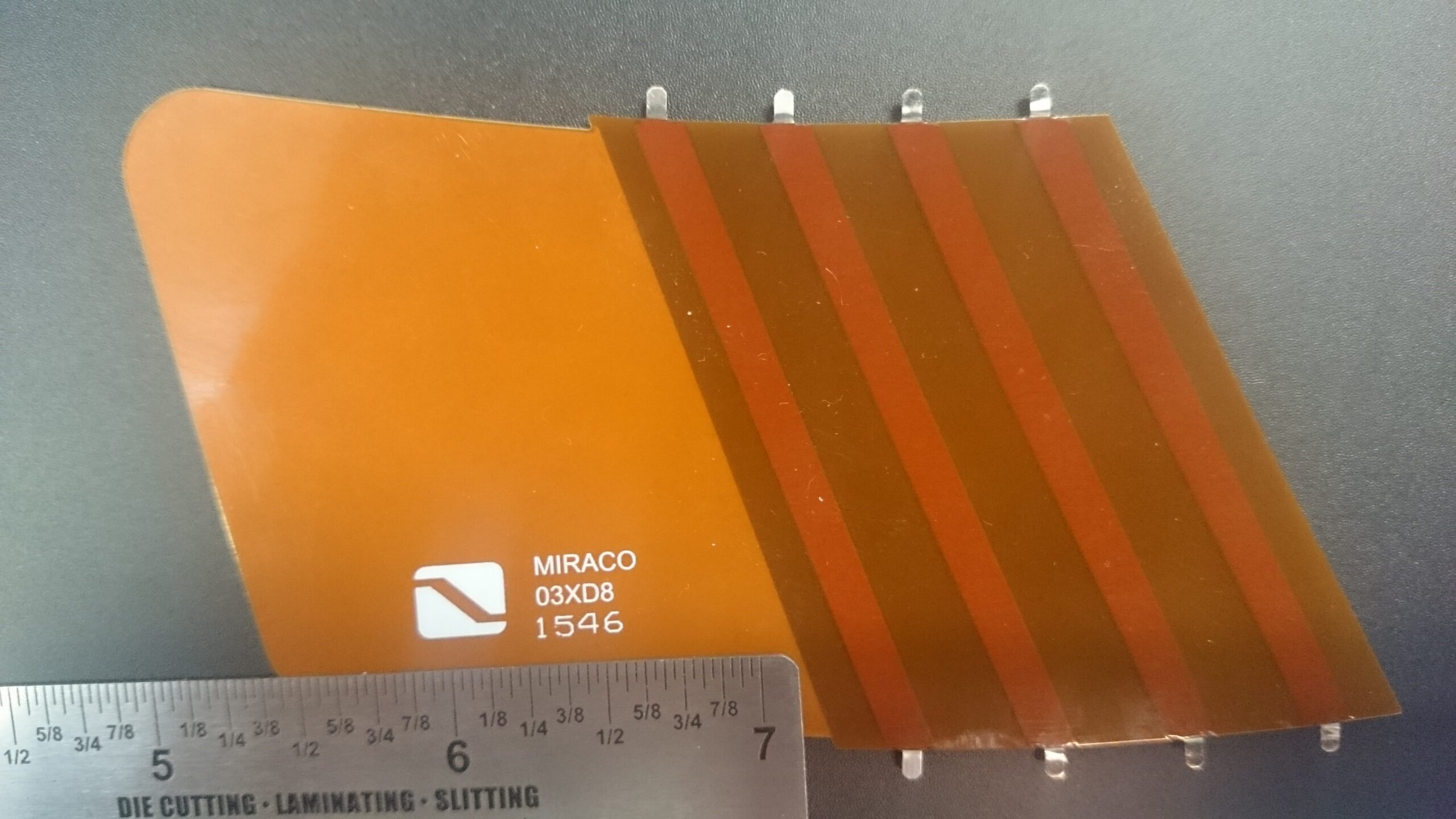
Using Heavy Copper PCBs in Power Distribution Systems
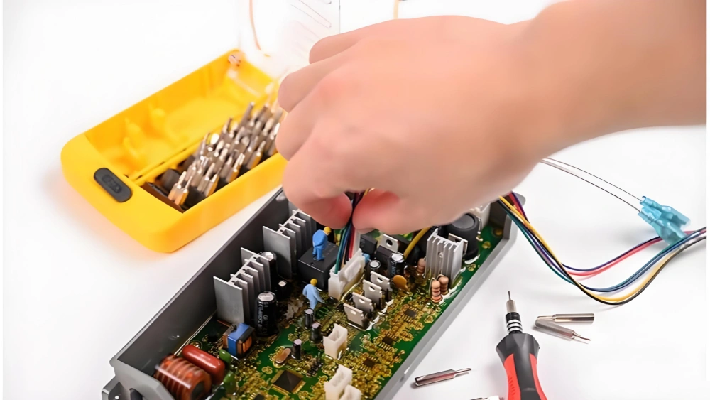
Modern electronic systems are moving toward smaller sizes and higher power density at an unmatched speed. For hardware engineers and product designers, managing extreme heat and high current carrying capacity in power distribution systems has become the line between product success and failure. When standard FR-4 material hits its thermodynamic limit, metal core PCB (MCPCB) combined with heavy copper technology becomes the key breakthrough. This high-power heat dissipation substrate not only completely changes the thermal conduction path, but also gives a physical guarantee for electrical stability in extreme environments. This guide explains the types, process flow, and key design rules of metal core PCB in detail, and shows you how to make the best strategic material choice in power distribution systems.
What Is a Metal Core PCB? (In-Depth Explanation and Its Importance)
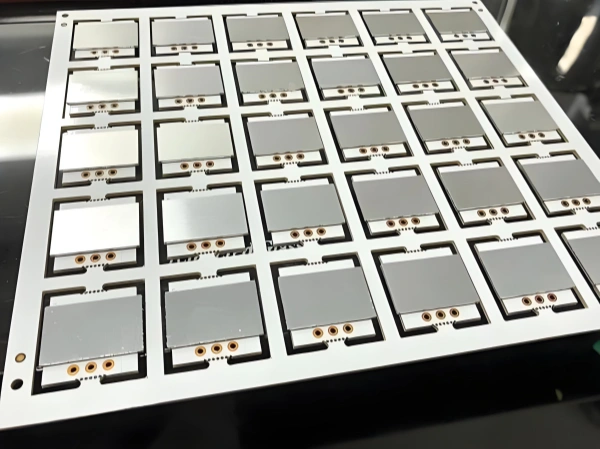
Simply put, a PCBA is a PCB plus assembly. A metal core PCB is a thermodynamic evolution of this basic structure. Its core architecture is made of three parts: a copper foil circuit layer on top, a high thermal conductivity dielectric layer in the middle, and a metal base plate (usually aluminum or copper) at the bottom.
Unlike standard woven glass epoxy resin (FR-4) PCBs, a metal core PCB plays a critical role in thermal management. It gives a reliable solution for applications that need efficient heat dissipation. In a power distribution system, high current flowing through traces creates large joule heat (I2R losses). If the heat cannot be removed quickly, it will cause dielectric layer breakdown, solder joint fatigue, or even system thermal runaway.
Understanding this topic is critical to your design success:
- Cost effectiveness: The initial manufacturing cost is higher, but the total system-level BOM cost drops significantly because you remove the need for external heat sinks or complex liquid cooling systems.
- Reliability: The service life of power semiconductors (such as MOSFETs and IGBTs) is extended greatly by keeping a lower junction temperature.
- Signal integrity: The metal base gives excellent grounding shielding. This reduces electromagnetic interference (EMI) from high-frequency power distribution switching.
Types and Material Components of Metal Core PCBs
In power distribution system design, choosing the right material base is the first step. Based on the heat load and mechanical needs of the application, there are several main variants:
| Type | Main Characteristics | Typical Thermal Conductivity (W/m·K) | Cost | Ideal Power Distribution Application |
|---|---|---|---|---|
| Aluminum PCB | Light weight, good machinability, cost effective. Supports surface finishing and high-temperature coating. | 1.0 - 3.0 | Low | LED driver power supplies, mid-power motor control, DC-DC converters. |
| Copper Core PCB | Excellent thermal conductivity. Supports complex heavy copper plating and cooling channel design. Heavier weight. | 3.0 - 8.0+ | High | Automotive powertrain systems, high-power inverters, solid-state relays. |
| Stainless Steel Base | Very high mechanical strength, strong vibration and corrosion resistance, but thermal conductivity is relatively poor. | 0.5 - 1.5 | Medium | Aerospace power distribution, power modules for extremely harsh environments. |
Besides the base material, the dielectric layer is the real core technology. It must keep electrical insulation and give very low thermal resistance at the same time. As we pointed out in our discussion on Copper Clad Laminate: The Backbone of PCB Manufacturing, the molecular structure of the base material directly decides its stability at high temperatures.
Process Flow and Working Principle of Metal Core PCBs
Making high-quality metal core PCBs needs very strict process control, especially when combined with heavy copper technology. Here are the core manufacturing steps:
-
Dielectric Layer Coating and Lamination
Evenly coat epoxy resin containing high thermal conductivity ceramic powder (such as alumina or aluminum nitride) on the metal base. This step must ensure no air bubbles in the dielectric layer, because any tiny air gap becomes a deadly thermal resistance point.
- Quality control tip: Follow the IPC-4101 standard. Use thermomechanical analysis (TMA) to check the glass transition temperature (Tg) of the dielectric layer. Make sure it is above 130°C to handle high-temperature working conditions.
-
Precision Copper Foil Lamination
Laminate copper foil with the dielectric layer through precision copper foil lamination. For power distribution systems, the copper foil thickness is usually between 3oz and 10oz, to carry tens to hundreds of amperes of current.
-
Heavy Copper Plating and Microvia Technology
For designs that need higher current density, apply heavy copper plating. At this stage, the factory also combines copper filling and microvia technology to strengthen the interlayer electrical connection and heat conduction in multilayer metal core boards. A deeper look at Heavy Copper PCB of Application in Electronic Manufacturing can help you better optimize the high-current trace topology.
-
Surface Finishing and Solder Mask
Apply high-performance surface finishing, such as electroless nickel immersion gold (ENIG), to stop copper surface oxidation and ensure soldering reliability of power devices. Then apply a solder mask layer and build solder mask bridges to prevent arc discharge between high-voltage nodes.
-
Shaping and Cooling Channel Design
For extremely high-power applications, the factory directly machines a cooling channel design on the base plate to support liquid cooling or forced air cooling. Finally, CNC milling shaping is done. For double-sided aluminum PCBs, a strict high-potential (Hi-Pot) test is performed.
Key Comparison: Standard FR-4 PCB vs. Metal Core PCB
In a power distribution system architecture, engineers must make a critical strategic decision. Here is an in-depth comparison between standard PCBs and metal core solutions:
| Evaluation Dimension | Standard FR-4 PCB | Metal Core PCB (Combined with Heavy Copper Technology) |
|---|---|---|
| Thermal Management Ability | Poor (~0.25 W/m·K). Relies on external heat sinks and via arrays. | Excellent (1.0 - 8.0+ W/m·K). Directly conducts heat to the metal base. |
| Current Carrying Capacity | Low. Limited by thin copper foil (usually 1oz - 2oz). Heats up easily. | Very high. Supports 3oz to 20oz or even thicker copper layers. |
| Mechanical Strength & Reliability | Easily delaminates under thermal shock. | Has enhanced anti-aging, anti-corrosion, and anti-interference ability. Adapts to high/low temperature, high humidity, and anti-vibration environments. |
| Manufacturing Cost | Low. Mature standardized process. | High. Special lamination and heavy copper plating processes raise manufacturing cost. |
| Signal Integrity (EMI) | Needs extra ground plane design to shield noise. | The metal base naturally acts as an excellent RF and EMI shielding layer. |
| Typical Thickness Range | 0.2–3.0 mm | 0.6–3.2 mm |
Key Design Rules and Integration Strategy
To maximize the effectiveness of a metal core PCB in a power distribution system, you need to follow these best practices:
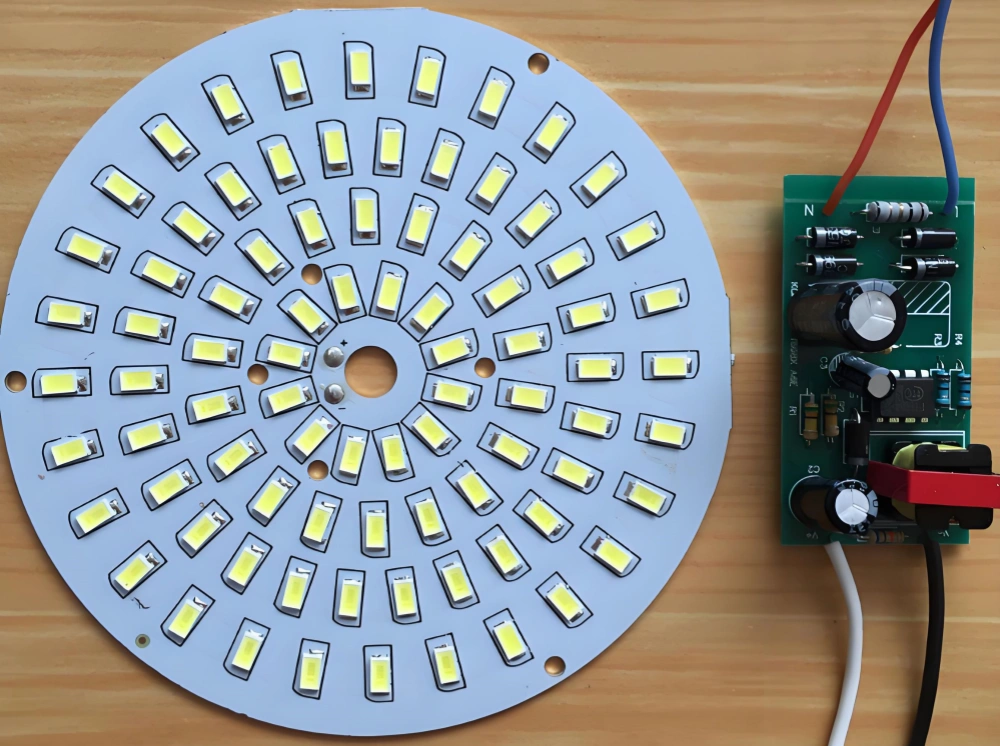
- Optimize trace topology: Do not use sharp-angled traces in heavy copper designs. Use teardrop designs to connect pads and traces. This stops stress concentration and cracking during thermal expansion and contraction.
- Match coefficient of thermal expansion (CTE): Power semiconductors (such as ceramic-packaged IGBTs) have a low CTE. Choosing a copper base plate (CTE about 17 ppm/°C) reduces solder joint fatigue failure in thermal cycles better than an aluminum base (about 23 ppm/°C).
- High-voltage isolation spacing: In power distribution systems, creepage distance and clearance are mandatory requirements. Use the high breakdown voltage of the solder mask and dielectric layer. Ensure there is enough safety distance between high-voltage nodes and the exposed metal base.
- Reinforced design for automotive-grade applications: Automotive power distribution systems are a typical battleground for metal core PCBs. The design must meet the strict needs of powertrain systems, such as battery management, motor control, and onboard chargers. Also, the system must support safety systems like airbags and ABS, as well as various sensor systems.
- Thermal via strategy: The metal core itself is the main heat conductor. But placing dense filled microvias directly under the top-layer component pads can further "pump" heat from hot spots into the metal core through the shortest path.
Conclusion and Strategic Business Transition
In modern power distribution systems, thermal management is no longer an after-the-fact fix. It is the core architecture that decides product performance and life cycle. From choosing a high thermal conductivity dielectric layer to applying heavy copper plating, the metal core PCB gives a solid, reliable, and highly integrated physical base for high-current, high-heat environments.
However, designing and making this complex substrate needs very high process precision and deep material science experience. As a partner, our factory handles this by combining advanced double-sided aluminum PCB manufacturing with heavy copper plating technology. This ensures your power distribution product runs with zero defects in the face of extreme temperature and vibration. FS PCBA specializes in turning thermodynamic design theory into mass-production reality. This ensures your product stands out in the market.
Ready to Upgrade Your Power Distribution System?
Is your high-power design being held back by the thermal bottleneck of traditional substrates? Contact our engineering team for a thermodynamic and electrical performance analysis tailored to your project. We offer a complete solution from material selection to high-performance surface finishing in the metal core PCB field.
Request a Free Quote and Explore Our Heavy Copper PCB ServicesFAQ
Yes. Single-sided aluminum PCBs are the most common, but advanced manufacturing processes support double-sided aluminum PCBs and multilayer designs. This requires drilling holes in the metal core and performing hole metallization insulation treatment. The technical difficulty is higher, but it greatly improves the wiring space for high-density power distribution systems.
This depends on your maximum steady-state current and the allowed temperature rise. Usually, power distribution systems use 3oz to 10oz copper thickness. If the current exceeds 100A, an extremely thick 20oz copper design may be needed, along with a special cooling channel design.
Because of their excellent high-temperature and anti-vibration ability, they are widely used in automotive powertrain systems (engine control, battery management, chargers), safety systems (ABS, parking sensors), and infotainment systems. Their enhanced anti-interference ability also protects sensitive in-vehicle communication networks.
For high-density power device soldering in power distribution systems, ENIG is usually the better choice. It gives a flat soldering surface and has better stability and reliability at high temperatures. In comparison, the uneven surface of HASL may affect the coplanarity of high-power surface-mount devices.
Table of Contents
- Metal Core PCB ဆိုတာဘာလဲ။ (အသေးစိတ်ရှင်းလင်းချက်နှင့် ၎င်း၏အရေးပါမှု)
- သတ္တု Core PCB များ၏ အမျိုးအစားများနှင့် ပစ္စည်းအစိတ်အပိုင်းများ
- သတ္တု Core PCB များ၏ လုပ်ငန်းစဉ်စီးဆင်းမှုနှင့် အလုပ်လုပ်ပုံနိယာမ
- အဓိကနှိုင်းယှဉ်ချက်- စံ FR-4 PCB နှင့် သတ္တု Core PCB
- အဓိကဒီဇိုင်းစည်းမျဉ်းများနှင့် ပေါင်းစပ်မှုဗျူဟာ
- နိဂုံးချုပ်နှင့် မဟာဗျူဟာမြောက် စီးပွားရေး အသွင်ကူးပြောင်းမှု
- အမြဲမေးလေ့ရှိသောမေးခွန်းများ
Tags
Related Posts
PCBA Prototype
October 23, 2026
PCBA Prototype
October 19, 2026