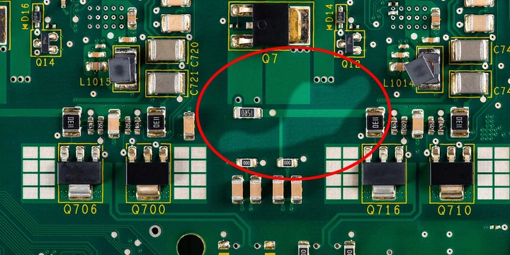
IPC-A-610: PCB Assembly Quality Acceptance Guide
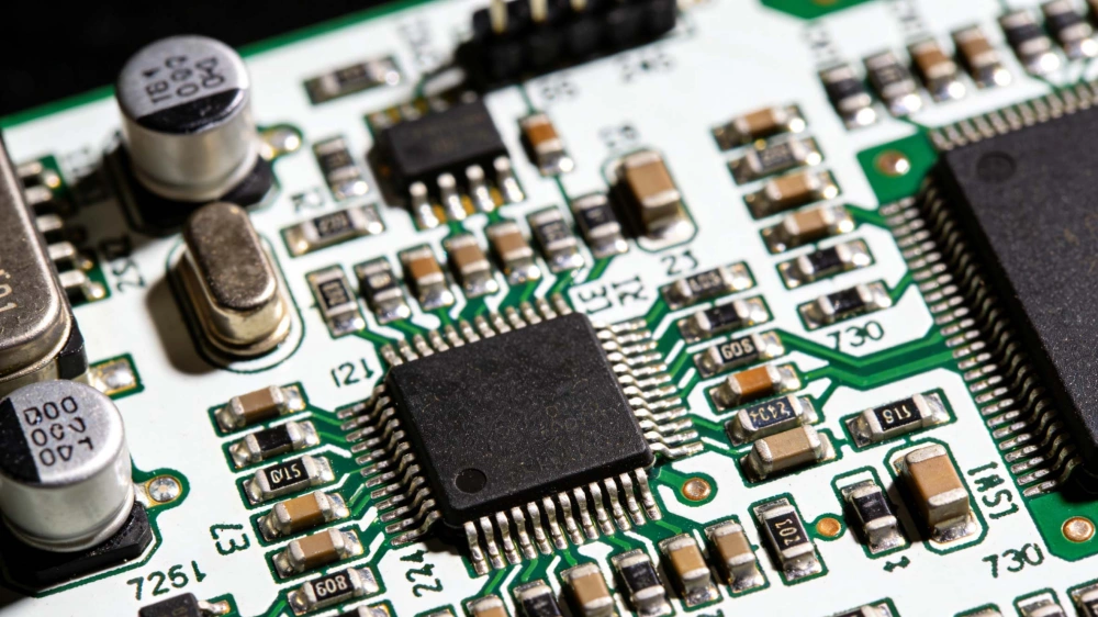
When a customer rejects a PCB assembly, the disagreement is rarely limited to one solder joint. More often, the root problem is that the buyer, contract manufacturer, and inspection team never aligned on what “acceptable” meant, which product class applied, or which revision governed the build. The IPC-A-610 acceptance standard gives electronics teams a shared language for evaluating workmanship and the acceptability of completed assemblies.
IPC describes IPC-A-610 as providing the requirements for acceptance of electronic assemblies. For production teams, however, using the document effectively requires more than asking a supplier to be “IPC compliant.” Engineers and quality leaders must define the applicable class, connect acceptance criteria to drawings and customer requirements, train inspectors, and preserve objective evidence. Procurement teams must ensure those expectations appear in the RFQ and supplier quality agreement.
This guide explains what IPC-A-610 does, how it fits into a practical PCB assembly quality-control system, and how teams can use a shared productivity platform to make inspection and corrective action more visible and repeatable.
What Is the IPC-A-610 Acceptance Standard?
IPC-A-610, formally titled Acceptability of Electronic Assemblies, is an industry standard used to evaluate whether an electronic assembly’s visible workmanship meets defined acceptance criteria. It supports inspection of assembled printed circuit boards and other electronic assemblies, including common surface-mount, through-hole, and mixed-technology configurations.
The standard gives inspectors visual references and acceptance categories for characteristics such as component mounting, solder connections, terminals, conductors, markings, and other assembly features. The purpose is not to make every board look identical. The purpose is to create consistent criteria for judging whether the assembly is acceptable for its intended product class and contractual requirements.
It is important to understand what IPC-A-610 is not. It is not a substitute for the product drawing, engineering change notice, bill of materials, approved deviation, or customer-specific requirement. It is also not a complete process-control manual. For example, a supplier may need separate process specifications for soldering materials and methods, design requirements for land patterns, board acceptability requirements, or rework and repair instructions. IPC notes that IPC-A-610 is developed in synergy with J-STD-001 and IPC/WHMA-A-620.
A useful working distinction is that IPC-A-610 primarily helps answer, “Is this completed assembly acceptable?” Process documents and manufacturing controls help answer, “How should we build it consistently?” Strong quality systems use both questions together.
IPC-A-610J and Product Classes
The current revision listed on IPC’s official product page is IPC-A-610J, published on March 1, 2024. IPC states that the revision incorporated input from participants in 31 countries and describes the document as the most widely used electronics assembly acceptance standard in the industry. Because standards can be revised, procurement documents and inspection plans should identify the exact revision rather than using only the phrase “latest IPC standard.” Always verify the current edition through the official IPC source before release.
IPC-A-610 defines three product classes. The class is not a ranking of supplier quality; it expresses the expected service environment, performance requirements, and consequences of failure. The user and supplier should agree on the class before production acceptance begins.
| Product class | General meaning | Practical quality implication |
|---|---|---|
| Class 1 | General Electronic Products | Assemblies where the principal requirement is function of the completed product. |
| Class 2 | Dedicated Service Electronic Products | Assemblies where continued performance and extended service are important, but uninterrupted operation is not always essential. |
| Class 3 | High Performance Electronic Products | Assemblies where continued or demanding performance is essential and equipment downtime or failure may carry significant consequences. |
ANSI’s overview explains that IPC-A-610J organizes criteria under Acceptable, Defect, and Process Indicator conditions. A process indicator may signal variation that should be monitored even when it does not automatically make the assembly rejectable. That distinction matters operationally: treating every process indicator as a defect can create unnecessary rework, while ignoring recurring indicators can allow process drift.
The class should be documented in the purchase order, quality agreement, inspection plan, and any electronic traveler. If a product contains different risk zones or customer-specific controls, document those exceptions explicitly instead of assuming the class alone resolves every question.
What Does IPC-A-610 Cover in PCB Assembly Inspection?
IPC-A-610 Quality Workflow
Component placement and orientation
Inspection begins before evaluating the solder joint itself. Confirm that components are present, correctly identified, properly oriented, and seated as intended. Polarity-sensitive parts, connectors, switches, and mechanically constrained components deserve special attention because an orientation error can create a functional failure even when the solder appears acceptable.
For SMT assemblies, inspect alignment, rotation, tombstoning, lifted leads, displaced parts, and evidence of disturbed placement. For through-hole components, check insertion, lead formation, retention, protrusion, and mechanical security according to the applicable criteria and product documentation. Use the assembly drawing, centroid data, BOM, and approved substitutions as companion records; visual inspection should not rely on memory or an outdated PDF.
Solder joints and workmanship
Solder inspection commonly evaluates wetting, fillet formation, bridging, excess or insufficient solder, dewetting, disturbed joints, cracks, and other visible anomalies. The relevant feature depends on the package and technology. A leaded through-hole joint, a chip component, a fine-pitch lead, and a bottom-terminated package cannot be judged with one generic visual rule.
For quality engineers, the practical lesson is to link inspection criteria to component families and defect codes. A photo of a suspected bridge should identify the reference designator, board serial number, lot, side of the board, and disposition. This turns a visual observation into traceable quality data that can support root-cause analysis.
IPC-A-610 should also be used alongside process controls such as solder-paste inspection, reflow-profile verification, placement-program validation, and automated optical inspection. Final acceptance is a gate, not the only source of process feedback.
SMT, through-hole, and mixed technology
A mixed-technology board may pass one inspection stage and still fail later because SMT and through-hole features introduce different risks. Define the inspection sequence so that operators know which characteristics are checked at printing, placement, reflow, insertion, selective soldering, wave soldering, hand soldering, and final assembly.
Automated optical inspection can improve coverage and repeatability, but it does not eliminate the need for qualified human judgment. Some features require review under appropriate lighting and magnification, while hidden joints or internal defects may require other inspection or test methods. Record the inspection method and any limitations rather than presenting “AOI passed” as proof that every requirement was verified.
Cleanliness, coating, marking, and physical damage
Assemblies may also require review for visible residue, contamination, conformal-coating conditions, damaged laminates, scratched solder mask, lifted pads, damaged components, incorrect labels, and missing traceability marks. These issues can be easy to overlook when inspection is narrowly focused on solder geometry.
The acceptance plan should state which characteristics are visually inspected and which require separate measurement or laboratory verification. For example, a visual assessment of residue is not automatically equivalent to a quantified cleanliness test. Likewise, a coating inspection should be tied to the specified coating material, coverage requirement, keep-out areas, and customer documentation.
Turning IPC-A-610 Into a Repeatable Quality Workflow
The standard becomes valuable when it is translated into controlled work. Start with a quality baseline: record the IPC-A-610 revision, product class, applicable drawings, customer-specific requirements, inspection stages, sample or 100% inspection rules, and escalation path. This baseline should be approved before the first production build.
Next, create a structured inspection checklist. Organize it by board identifier, assembly side, component family, operation, characteristic, acceptance status, inspector, date, and evidence link. Avoid copying large sections of the copyrighted standard into an internal checklist. Instead, reference the licensed document and capture the internal decision needed at that operation.
When a defect is found, create a nonconformance record with a stable identifier. The record should include a clear description, board or lot traceability, defect category, photographs, immediate containment, responsible owner, due date, disposition, and verification of corrective action. This prevents a common failure mode: a defect is discussed in email, reworked, and then disappears from the quality history.
A team productivity platform can support this workflow by connecting the inspection checklist to tasks, evidence, and decisions. Engineers can assign a technical review; procurement can notify the supplier; quality can approve the disposition; and manufacturing can verify the next build. A dashboard can show open NCRs by supplier, product, defect type, aging, and recurrence. The platform does not determine IPC acceptance by itself. It makes the human process around the standard more coordinated and auditable.
What Procurement Teams Should Put in an RFQ
“Build to IPC-A-610” is a useful starting phrase, but it is not a complete acceptance requirement. An RFQ or supplier quality agreement should identify the applicable revision and product class, define precedence when the drawing and standard differ, and require the supplier to disclose proposed deviations or substitutions.
Ask the supplier to explain how inspectors are trained and how inspection evidence is retained. Request sample inspection reports, traceability fields, first-article procedures, change-notification rules, and the process for handling defects and rework. If the product is safety-critical, harsh-environment, or regulated, include the additional customer and regulatory controls rather than assuming Class 3 alone defines the complete quality system.
A procurement scorecard should evaluate both output and process. Useful measures include first-pass yield, recurring defect rate, response time for NCRs, corrective-action effectiveness, on-time delivery of quality records, and change-control discipline. These measures create a more reliable supplier conversation than a one-time certificate or an undocumented statement of compliance.
Common IPC-A-610 Implementation Mistakes
The first mistake is treating IPC-A-610 as a universal design or manufacturing specification. Acceptance criteria cannot correct an ambiguous drawing, an unapproved component substitution, or a missing process window. Resolve those upstream issues before inspection.
The second mistake is failing to state the product class. Different classes can change the acceptability decision, so leaving the class implicit invites disputes at final inspection.
The third mistake is using obsolete documents. Quality teams should control revisions for the IPC standard, drawings, BOM, inspection programs, and internal checklists. A shared workspace with owners and review dates can make document drift visible.
The fourth mistake is confusing a process indicator with an automatic reject, or treating an acceptable visual condition as proof of long-term reliability. Use the standard’s categories correctly and supplement visual acceptance with electrical, mechanical, environmental, or functional testing when the product risk requires it.
Practical Implementation Checklist
Before production, confirm the IPC-A-610 revision, product class, customer requirements, and document precedence. During production, verify that trained inspectors use the approved checklist and that AOI, X-ray, electrical test, and human inspection results are clearly distinguished. When a nonconformance occurs, capture evidence, contain affected material, assign an owner, document disposition, and verify corrective action. After the build, review recurring defects and update the process rather than merely closing individual records.
The most effective teams treat IPC-A-610 as a shared operating language. Engineers define the technical interpretation, quality controls the evidence and disposition, procurement aligns the supplier contract, and manufacturing feeds process learning back into the line. A productivity platform for teams can provide the connective tissue: one place for checklists, records, conversations, approvals, and deadlines.
Conclusion
The IPC-A-610 acceptance standard is most useful when it is applied as part of a complete PCBA quality system. It helps teams evaluate electronic assemblies consistently, but the final outcome also depends on the product class, current revision, drawings, customer requirements, process controls, inspection capability, and traceable decision-making.
For PCB assembly engineers and quality engineers, the priority is to translate the standard into clear inspection points and defensible evidence. For procurement teams, the priority is to put those expectations into the RFQ and supplier agreement. For electronics manufacturers, the priority is to connect inspection findings to corrective action and continuous improvement. When those activities run in a shared, revision-controlled workflow, IPC-A-610 becomes more than a document on a shelf: it becomes a practical foundation for reliable assembly quality.
Note: IPC-A-610 is a copyrighted industry standard. This article summarizes its role and does not reproduce the standard’s proprietary illustrations, tables, or exact acceptance dimensions. Use the current authorized IPC publication and applicable customer requirements for production decisions.
FAQ
No. They are related but serve different purposes. IPC-A-610 focuses on acceptability of completed electronic assemblies, especially the visible characteristics used during inspection. J-STD-001 addresses requirements for soldered electrical and electronic assemblies and is commonly used to define process and material requirements. The correct relationship should be established in the customer and supplier documentation.
The product user and supplier should select the class based on the intended use, service environment, performance expectations, and consequences of failure. Class 1, Class 2, and Class 3 are not simply “low,” “medium,” and “high” supplier-quality levels. Document the selected class in the purchase order, quality agreement, and inspection plan.
No. Referencing IPC-A-610 does not by itself certify a supplier, process, product, or individual inspector. Supplier qualification should also review training, process capability, traceability, test coverage, corrective-action performance, and customer-specific requirements.
No. Visual acceptance and functional testing answer different questions. A board can appear acceptable while containing an electrical, software, hidden-joint, or environmental issue. Define electrical, mechanical, environmental, and functional tests according to product risk and customer requirements.
A team platform can organize revision-controlled checklists, inspection evidence, NCRs, owner assignments, approvals, supplier communication, and corrective-action deadlines. It should support the quality process rather than replace the licensed standard or qualified engineering judgment.
Tags
Related Posts
PCBA Prototype
September 8, 2026