
Rigid-Flex PCB Bend Radius Guide
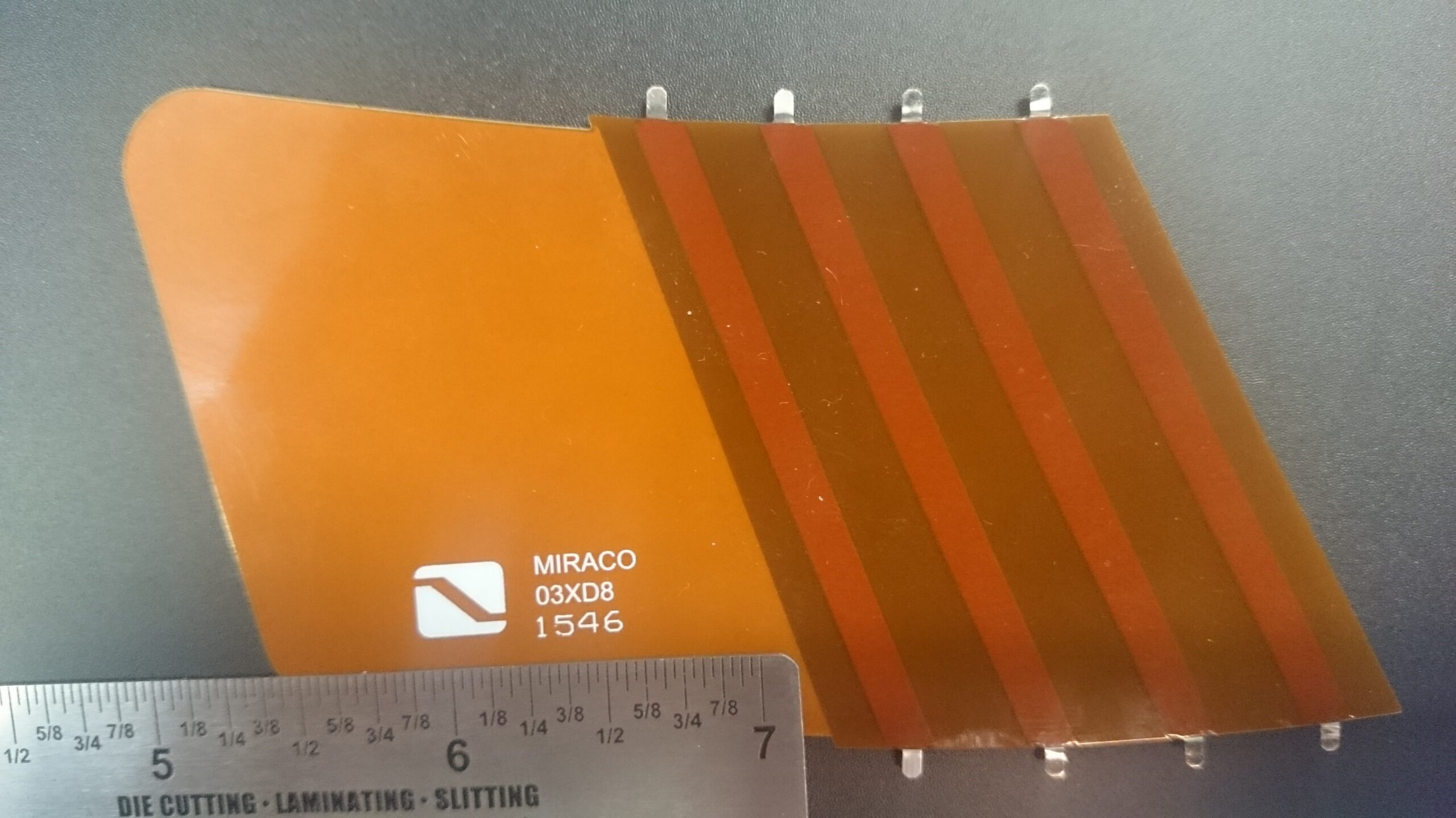
The right rigid-flex PCB bend radius depends on the finished thickness and construction of the flex region, how it moves, and the life it must achieve. A thickness multiplier can help screen a design, but the released radius needs to match the reviewed stackup, installed geometry and validation plan.
Start by separating an installation bend from movement during operation. Then calculate with the local flex thickness, check the space and length needed for the bend, and review routing and stiffness changes around it. This guide follows that sequence, with a worked example and a DFM checklist you can use before sending the design for fabrication.
Understand Bend Radius
Radius, Angle and Bend Length
A bend radius describes the curve, but drawings and CAD models must use the same reference. Here, inside radius (R) means the radius measured from the bend’s inner surface to its center of curvature. Bend angle is the change in direction through the curve. Bend path length is the distance measured along the flex through the curve; it depends on both radius and angle. These describe different parts of the geometry, so a radius alone does not define the whole bend. Altium’s bend guidance treats location, radius and angle as separate bend properties.
Use the Flex Thickness
Use the finished local flex thickness (t) through the bend: count every layer present there, including copper, dielectric, coverlay and bonding layers where used. Do not substitute the rigid section’s overall board thickness. During bending, material at the inner surface compresses while material at the outer surface stretches. The neutral axis lies between these regions, but an asymmetric stack can shift it away from the geometric mid-plane. Altium’s mechanical design discussion explains why thickness, radius and conductor position matter.
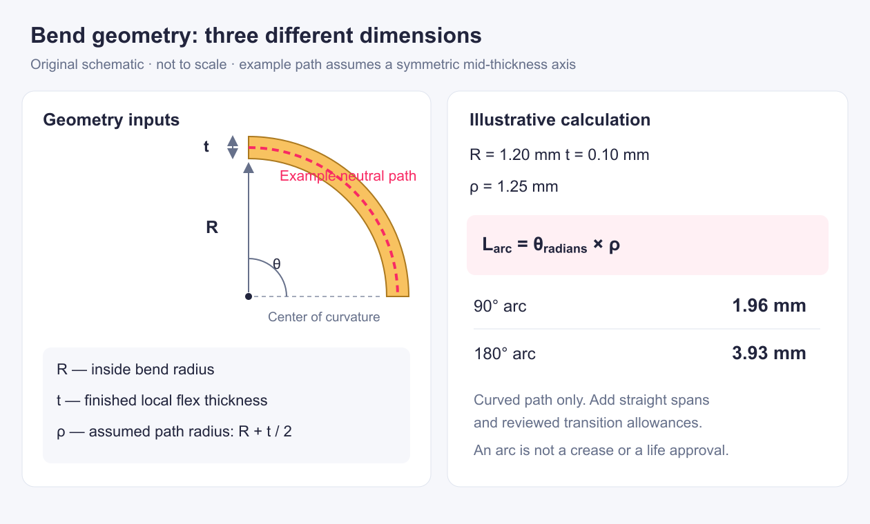
Original illustration. The example neutral path assumes a symmetric midpoint; dimensions are not a bend-life approval. Open full-size diagram
Define the Bend Application
Before choosing a rigid-flex PCB bend radius, define what the flex region will do after assembly. A bend made once to fit an enclosure has different demands from one that moves during operation. Service access may add occasional handling. Record these uses separately: a successful installation bend does not establish durability under repeated motion.
Bend to Install
For an installation-only bend, document the assembly path, bend direction, final shape, clearance, and temperature range. Check for interference during installation as well as in the final position. If service manipulation is expected, record its direction and frequency rather than labeling the region “static.”
Repeated Flexing
For operating motion, define the path and direction, expected cycle count, temperature range, and space for the moving loop. Include nearby parts, stops, and any twisting or out-of-plane movement. The review needs both the motion requirements and the proposed flex construction.
| Use case | Inputs to record | Review priority |
|---|---|---|
| Installation-only | Assembly path, bend direction, clearance, temperature | Fit and interference |
| Service manipulation | Access path, direction and frequency, temperature | Reversals or disturbance of installed shape |
| Operating motion | Cycle count, path, direction, temperature, moving space | Construction, conductor placement, repeated-motion review |
Do not use a universal cycle-count cutoff to classify a bend. Define the duty and have the proposed construction reviewed against it.
Estimate the Minimum Radius
Use Multipliers Carefully
A first-pass relationship is R_screen = k × t: t is finished flex thickness through the bend, and k depends on construction and motion. Treat the result as a screening radius, not a released design limit.
The following screening values come from published flex design guidance. They are starting points for the named construction and use:
| Application and construction | Screening multiplier |
|---|---|
| Static, single-sided flex | 6 |
| Static, double-sided flex | 12 |
| Static, multilayer flex | 24 |
| Dynamic flex, where the supplier’s scope fits | 100 |
These values reflect one supplier’s assumptions. Other published tables give different ranges, including 3–6t for single-sided and 20–40t for dynamic flex (flex-length FAQ). Do not average recommendations or treat them as interchangeable standards. Select a multiplier for the actual stack, materials, bend direction, and motion.
A Worked Example
Suppose a hypothetical two-conductor flex has a finished bend-region thickness of 0.10 mm and is folded once during assembly. If the fabricator agrees that static double-sided 12t is a suitable screening basis:
R_screen = 12 × 0.10 mm = 1.20 mm
Confirm the fabricator’s radius convention before applying it to tooling or enclosure geometry. At 0.12 mm finished thickness, the same multiplier gives 12 × 0.12 mm = 1.44 mm. Use finished bend-region thickness for t, rather than copper or film thickness alone. This arithmetic does not qualify the stack or approve 1.20 mm as a minimum.
Applying 100t dynamic screening to 0.10 mm gives 10 mm, not a cycle-life guarantee. Repeated motion needs design review and representative testing; agree on test path, radius, speed, and required cycles with the fabricator and product team.
When an Estimate Is Not Enough
Use the multiplier to screen the package envelope and flag tight bends. Before release, ask the fabricator to review the stack, bend geometry, rigid transitions, radius convention, and manufacturing constraints. For moving flex, define the motion and required endurance, then test a representative assembly. The calculation is screening guidance, not a universal IPC requirement or proof of service life.
Check the Bend Geometry
A radius is only part of the package envelope. The flex also needs developed length for the curved portion, adjoining straight portions, and transitions into the rigid sections. Check the complete shape against the enclosure and nearby components, then review the bend definition with the fabricator.
Allow Enough Flex Length
For a first-pass geometric estimate, use the illustrative values R = 1.20 mm inside radius and t = 0.10 mm uniform flex thickness. Assume the neutral path lies at the thickness midpoint: its radius is ρ = R + t/2 = 1.25 mm. For a circular bend, path length is L = θρ, with θ in radians. A 90° arc is about 1.96 mm; a 180° arc is about 3.93 mm.
These are arc lengths for the assumed neutral path, not total flex lengths or bend-life limits. Add straight lengths to reach the rigid sections and account for transition geometry. Derive any additional allowance from the mechanical design and fabricator review; do not assume a clearance. In an asymmetric construction, the actual neutral path may not lie at mid-thickness. Use suitable stackup analysis instead of treating the inside radius as every layer’s path radius.
Check the Installed Shape
Review the flex in its intended installed position and specified motion. Define the bend location, radius convention, angle, affected width, and fold order. Include the rigid-flex transition and nearby hardware in fit review. Review the enclosure and stackup together. A successful CAD fit check does not establish fatigue performance. This estimate does not approve a crease or forced fold. Validate the finished shape and motion under representative conditions.
Choose the Flex Construction
Copper, dielectric, adhesive, and coverlay layers determine how thick and stiff the flex region becomes, and where its conductors sit relative to the neutral bending axis. Choose a construction for the motion and electrical load, and ask the fabricator to review the finished stackup.
Copper and Plating
Rolled-annealed (RA) copper is a common choice for flex circuits, while electrodeposited (ED) copper is not automatically unsuitable for repeated movement. Some foil manufacturers offer ED foils with grain structures intended for flexing. Confirm the specific foil grade and finished construction; a foil coupon result is not a lifetime rating for the assembled circuit. Copper-foil manufacturer guidance
Specify finished copper thickness, not only the starting foil weight. Depending on the fabrication process, additional copper plating can make the finished conductors thicker than the base foil, changing resistance as well as stiffness and strain distribution. More copper can help meet electrical resistance targets, but it also makes the bend region less compliant. Review the final copper pattern and plating build with the fabricator, especially where plated features approach a moving bend.
Coverlay and Adhesives
Flex coverlay insulates and protects flex conductors. Its dielectric and adhesive layers add to the local stack thickness, so include them when reviewing the bend construction. An adhesiveless copper-clad laminate can reduce adhesive within the base laminate, but it does not mean the completed flex has no adhesive: coverlay or bonding layers may still use adhesive. Confirm each layer and its thickness in the proposed stackup. Adhesiveless laminate product information
Multilayer Flex Regions
A bonded multilayer flex region behaves as a constrained stack; its layers should not be assumed to slide freely during bending. Added layers generally increase thickness and stiffness, while an asymmetric stack can place the neutral axis away from the geometric center. That changes which conductors see more tension or compression.
For applications with multiple flex ribbons, distinguish a bonded stack from separate ribbons that can move independently. Equal-length ribbons following different radii can create slack in one path and tension in another. A bookbinder construction uses different ribbon lengths to accommodate different path radii; spatially separating ribbons is another option. Both approaches need fabricator review for the actual routing and motion. Construction overview
Route the Bend Area
Mark the active bend from the mechanical motion envelope before routing it. Arrange traces and copper features to limit local stiffness changes and stress concentrations while preserving the circuit’s electrical behavior.
Trace Direction and Shape
Where a connection must cross the bend, route it across the bend axis using smooth, continuous geometry. Avoid sharp corners, neck-downs, sudden width changes, and unnecessary jogs in the active area. Gradual transitions help avoid concentrating strain at one point; the exact geometry should be checked against the fabricator’s construction and the product’s motion.
For a two-layer flex, traces that overlap directly can create a locally stiffer strip. Stagger them where the circuit and stack-up allow, then review the effect on routing length, impedance, coupling, and return-current paths. A stagger is a mechanical option, not a rule to apply if it compromises signal integrity. Check copper redistribution electrically as well as mechanically; rigid-flex design guidance discusses staggered routing and gradual geometry changes.
Vias, Pads and Components
Keep vias, component pads, and mounted components out of the active bend whenever the layout permits. These features interrupt the flexible copper geometry or add local stiffness, so place them in a rigid region or a flex area that remains outside the moving bend. Check the full motion envelope rather than only the board’s flat outline: a feature near the nominal bend can enter the working area as the product moves. Review nearby stiffness transitions as well as the bend itself.
Planes and Return Paths
Copper planes affect both bending stiffness and electrical performance. A solid plane may support a continuous reference path but add copper across the bend; a mesh can reduce copper coverage, yet its openings and remaining copper still affect stiffness, impedance, and return-current continuity. Do not assume that meshing makes a plane suitable for every dynamic flex design.
The cited two-layer dynamic construction guidance advises against both solid and hatched plane fills in the dynamic region. That is a construction-specific recommendation, not a universal prohibition. If the design needs a reference plane or shielding through a moving bend, review the electrical requirement with the fabricator and evaluate the resulting stack-up and bend behavior together (dynamic flex design guidance).
Protect the Transition
Rigid-Flex Boundaries
A rigid-flex board has three mechanically distinct areas: the active bend, the rigid-to-flex transition, and any stiffener edge. The active bend is the span intended to take curvature during forming or motion. The transition is where the flexible stack leaves the rigid section; local layer termination, coverlay and abrupt geometry changes can concentrate deformation there. A stiffener edge is a separate stiffness step, even when it sits inside or near the flex region.
Show these boundaries on the fabrication and assembly drawings, along with the intended bend direction, finished stackup and motion. Ask the fabricator to review coverlay termination and overlap against the actual construction. Check that adhesive does not squeeze into the moving span, and that rough transition edges will not abrade it. If the assembly needs strain relief, define its material and placement with the fabricator and mechanical team; added adhesive is not a universal fix. Keep motion from pinching at the rigid-to-flex step, and confirm the transition under representative movement.
Stiffener Edges
A stiffener can support a connector or other component, but it moves the stiffness boundary to its edge. Keep the intended flexing motion clear of that edge where the assembly permits, and check whether the proposed stiffener changes the unsupported span or transfers load into the transition. There is no single overlap or clearance that fits every stackup and motion. Record the stiffener material, thickness, extent and edge location, then review them with the board supplier and assembly team. Include connector loads, enclosure constraints and FPC assembly handling in that review.
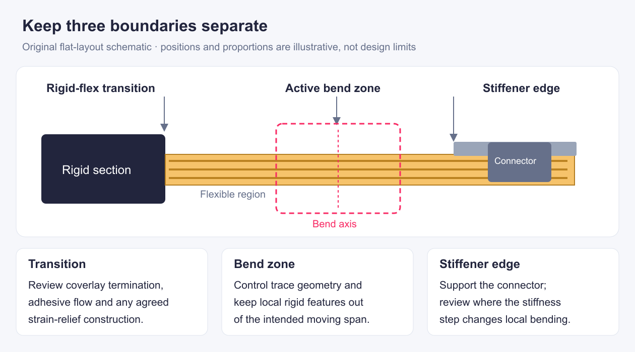
Original illustration. Keep the active bend, rigid-flex transition and stiffener edge distinct; clearances require review for the actual construction. Open full-size diagram
Validate the Design
Mechanical Fit Checks
Begin with required motion. A paper section or CAD sweep can reveal interference, a bend entering a rigid region, or a path that will not fit the enclosure. Check the full movement envelope against the housing, connectors, fasteners, and nearby components. This establishes geometric fit, not repeated-motion durability. Coordinate the enclosure, stackup, and flex path with the fabricator before design freeze, consistent with rigid-flex mechanical design guidance.
Build representative samples if fit or construction remains uncertain. Record the stackup and bend location; inspect whether the sample follows the intended path without pinching, twisting, or loading the rigid-to-flex transition. Static fit can confirm closure and movement through the required range, but cannot establish fatigue life.
Bend-Life Testing
Treat endurance as a defined experiment, not a universal pass count. Specify construction, sample count, radius, angle or motion direction, rate, fixture, environment, cycles, and application-relevant failure criteria. If continuity matters during motion, define monitoring and the interruption or resistance change that constitutes failure; no universal threshold fits every circuit.
The public historical IPC-TM-650 2.4.3.1C method, dated March 1991, evaluates flexural fatigue around a specified mandrel radius. It treats electrical discontinuity as failure and records cycles to failure under the stated conditions. Its coupon setup, including fully reversed flexing, compares constructions in that setup; it does not translate directly to product service life when radius, restraint, motion, or environment differs.
Use a test to answer its defined question: whether the selected construction meets an agreed criterion under representative conditions. Report the setup, observations, and failures with the result. A passing coupon or fit review supports a design decision; neither guarantees product lifetime.
DFM Checklist
A radius value helps only when the fabricator can relate it to the finished construction and intended motion. Define the bend location, radius, angle, affected width, and fold order consistently in CAD and drawings; include region dimensions, stackup, and assembly notes. Manufacturing documentation guidance describes the information needed to communicate the construction.
| Provide with the design package | Confirm during DFM review |
|---|---|
| Region map and stackup for each rigid and flex area | Materials and construction match the intended bend region |
| Finished-thickness target and tolerance | Whether the specified tolerance is compatible with the proposed construction |
| Copper type/grade and plating details | The fabrication assumptions used for the bend area |
| Bend drawing: location, radius convention, angle, direction, fold order, and affected width | Geometry is unambiguous and matches the assembly sequence |
| Transition details, coverlay openings, and stiffener extents | Local stiffness changes and support are understood |
| Electrical requirements, inspection points, and requested test conditions | Acceptance criteria and validation conditions are defined before build |
Mark unknowns explicitly rather than relying on a default radius or assumed motion. Review the complete package with the fabricator before release, then validate the assembled design under representative use conditions. For a project-specific review, share the package through GreatPCB rigid-flex PCB service.
FAQs
What is the minimum bend radius for a rigid-flex PCB?
There is no universal minimum radius for rigid-flex. The suitable value depends on whether the bend is formed once or moves in service, as well as the finished stackup and conductor placement. Begin with the fabricator’s guidance and validate the application.
Which thickness should I use in the calculation?
Use the finished local flex thickness through the bend, including the layers and materials present there. Nominal or unfinished values may misstate geometry. Confirm the stackup with your fabricator, and use one radius convention consistently in CAD and drawings.
Can I use a static bend rule for repeated flexing?
No. A static bend is formed for installation and stays in place; repeated flexing adds fatigue. Use guidance for the expected motion and evaluate the complete construction. Thickness, radius, and conductor position affect strain, so a static screening rule cannot establish dynamic durability.
Can a rigid-flex PCB be folded to a sharp crease?
A 180-degree bend describes an arc; it does not mean a sharp crease. Creasing concentrates deformation and needs a construction and forming process designed for that outcome. Ask the fabricator to review this special requirement; a radius-based bend does not automatically produce a crease.
Does meeting the bend radius guarantee flex life?
No. Radius alone cannot guarantee flex life. Life depends on construction, conductor placement, motion, and application conditions. For repeated movement, agree on representative validation with the fabricator. The public IPC-TM-650 2.4.3.1C method discussed above records cycles to failure under specified test conditions; coupon results do not automatically predict product life.
Image credit: Billpnh · CC BY-SA 4.0.
Related Posts

PCBA Prototype
September 8, 2026