
PCB Manufacturing and Assembly Capabilities
GreatPCB provides PCB fabrication and assembly services for prototypes and production projects. Review the capability areas below to find the specifications relevant to your design, from rigid, flexible and metal-core boards to SMT assembly and inspection.
Manufacturing limits depend on the board construction and the combination of requirements. Send your fabrication and assembly files for a review of your specific project.
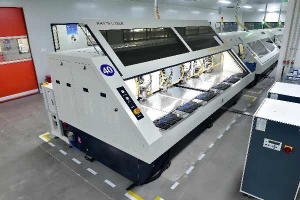
Choose the Capability for Your Project
Rigid PCB Manufacturing
Review layer count, trace width and spacing, drilling, copper and controlled impedance for rigid PCB designs. The rigid PCB capability table separates prototype and production specifications.
Flex and Rigid-Flex PCB Manufacturing
Flexible circuits and rigid-flex boards use different structures and may have different layer, material and thickness requirements. Explore our flex and rigid-flex capability table.
Metal-Core PCB Manufacturing
Metal-core boards support applications where heat transfer is an important part of the design. Review base material, board thickness, copper and hole requirements in our metal PCB capability table.
SMT Assembly and Inspection
Review component packages, board size and assembly requirements together with the inspection plan. Our SMT capability page covers equipment, package sizes and assembly options.
Rigid PCB Manufacturing Capabilities
Our published rigid PCB table lists the following values for prototype and production orders:
| Item | Published rigid PCB specification |
|---|---|
| Copper layers | 1–30 layers |
| Minimum trace width / spacing | 3 / 3 mil |
| Minimum mechanical drill size | 0.2 mm |
| Minimum laser drill size | 0.1 mm |
| Controlled impedance | ±7% for prototypes; ±10% for production |
These are individual specifications, not a guarantee that every minimum or tolerance can be combined in the same design. Material, copper, stackup and via structure all affect manufacturability. Consult the complete rigid PCB table for the conditions and additional specifications.
Flexible and Rigid-Flex PCB Capabilities
The current flex PCB capability table lists 1–12 layers for flexible boards and 2–18 layers for rigid-flex boards. It also describes materials, copper weights, feature sizes and thickness ranges for different constructions.
For a flex or rigid-flex project, provide a stackup and identify the areas that bend, the installation shape and whether bending is occasional or repeated. The flexible section, rigid sections and transition areas need to be considered together. Learn more about flexible PCB manufacturing and rigid-flex PCB manufacturing.
Metal-Core PCB Capabilities
Our metal PCB capability table lists aluminium-, copper- and iron-based materials and 1–4 layers. Actual material, layer count and dimensions depend on the construction.
For thermal designs, identify the base material, insulation and copper requirements alongside the intended heat path. Drill size in the detailed table depends on finished board thickness; use the complete table and fabrication drawing to review the applicable conditions.
SMT Assembly and Inspection Capabilities
GreatPCB supports single- and double-sided SMT and through-hole assembly. The SMT capability page lists 0201 as the smallest chip size and describes board dimensions, package options and inspection equipment.
Assembly planning also depends on component packaging, access and placement requirements. Our services include through-hole and mixed-technology assembly and BGA assembly. Inspection and testing can be selected for the project: explore PCB assembly testing to understand what AOI, X-ray, electrical and functional checks address.
How to Check Your Design Against Our Capabilities
1. Identify the board construction. State whether your project uses a rigid, flexible, rigid-flex or metal-core PCB and provide the layer count and stackup.
2. Mark critical fabrication requirements. Include materials, copper, finished thickness, holes, impedance targets, surface finish and any special tolerances.
3. Add assembly information if needed. Supply a BOM, placement file and assembly drawing, and identify any customer-supplied components.
4. Define inspection and delivery requirements. Tell us about the quantities, testing procedures, acceptance criteria and reports needed for the build.
The PCB manufacturing services overview can help you find the appropriate board type. Our PCB stackup and impedance control pages explain two common areas to review before fabrication.
Frequently Asked Questions
Do these capability values apply to every board type?
No. Rigid, flexible, rigid-flex and metal-core boards have different structures and manufacturing constraints. Use the table for the relevant board type, and review combinations of requirements against the actual design.
Can a PCB combine several advanced requirements?
Depending on the construction, a design may combine features such as fine traces, controlled impedance, special materials or different via types. Share the complete stackup and fabrication requirements so the combination can be reviewed together.
What files should I send for a capability review?
Send the fabrication files, drill data, stackup and fabrication drawing, together with quantities and any special manufacturing or testing requirements. For assembly, add the BOM, placement file and assembly instructions.
Can fabrication and assembly be quoted together?
Yes. Provide both the PCB fabrication package and the assembly information. Identify the parts you will supply and those you would like GreatPCB to source.
Discuss Your PCB Requirements
Send your design files, quantities and critical specifications. Our team can review the requested board construction and assembly scope and discuss the quotation with you.